Chapter 5: Filtering Estimation and Low-Level Control
After completing the 3D modeling and motion modeling of the vehicle, the next step is to develop a low-level control system to ensure the vehicle can stably follow predefined commands. For the low-level control system, filtering estimation algorithms are crucial, as they extract precise and smooth state estimates from noisy and erroneous sensor data; low-level control algorithms, based on the filtering estimates and combined with user input commands, drive actuators and power systems to achieve stable vehicle control. This chapter first reviews the relevant background theory of filtering and control, then introduces the design methods, development procedures, and tuning strategies for filters and controllers.
5.1 Background and Theory
In intelligent unmanned systems, the control layer is typically divided into two hierarchical levels: the low-level control system and the high-level control system. The core components of the low-level control system include vehicle filtering and control (covered in this chapter), external control and trajectory planning (detailed in Chapter 6), and health management and safety decision-making (detailed in Chapter 7). Its primary objective is to construct a foundational intelligent agent composed of the vehicle body and control systems, enabling stable and reliable pose and position state perception and control, while receiving decision-making commands from the high-level system via standardized external interfaces.

5.1.1 Filtering Estimation Principles
In intelligent unmanned systems, filters and controllers constitute the two core modules of the low-level control system, directly impacting system stability, accuracy, and autonomy. Specifically, the controller is responsible for real-time adjustment of the unmanned system’s spatial position and attitude, enabling it to follow a predefined trajectory or target; the filter fuses data from multiple sensors to provide accurate state estimation (including pose, velocity, etc.), compensating for noise and errors, thereby delivering reliable state feedback to the controller. These two technologies complement and collaborate with each other, ensuring the unmanned system efficiently and stably executes tasks in complex, dynamic environments.
A typical automatic control system comprises three core components: the plant, the controller, and the feedback loop. The controller computes control commands based on the deviation between the desired value and the actual output; the plant executes corresponding actions according to the control commands; the feedback loop measures the actual state of the plant via sensors and feeds this information back to the controller, forming a closed-loop control system.
5.1.2 Controller Design Fundamentals
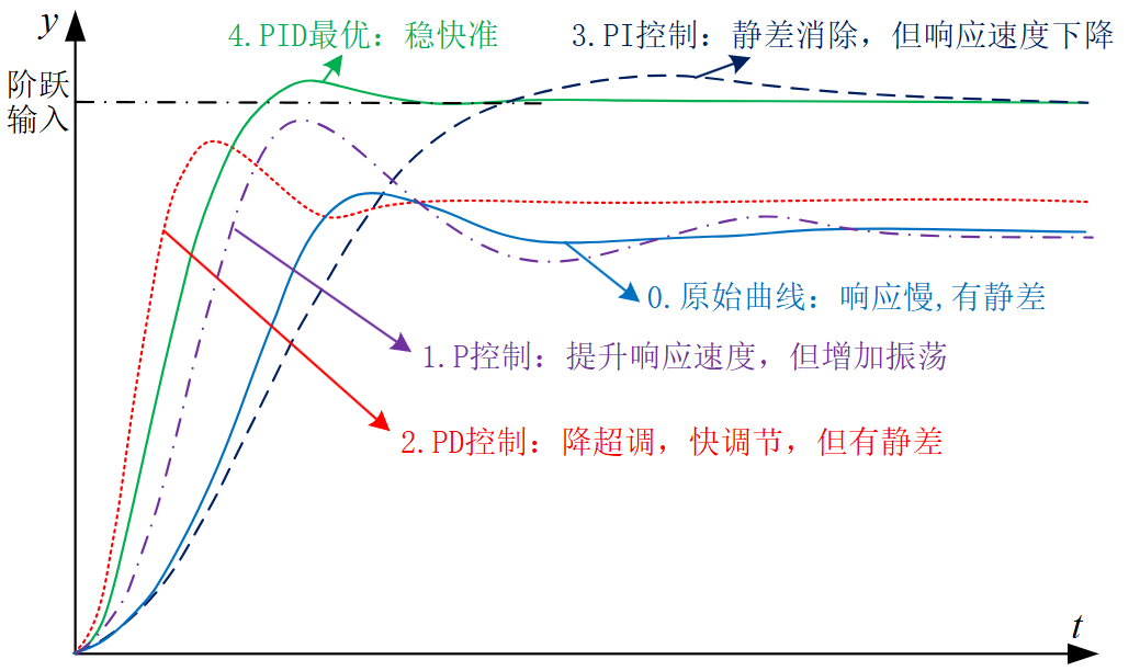
In the field of unmanned systems, common control algorithms include PID control, fuzzy control, adaptive control, and sliding mode control. Among them, PID control is widely adopted due to its simple structure and ease of implementation. A PID controller consists of three components—proportional (P), integral (I), and derivative (D)—which collectively regulate the error based on its past, present, and future trends to achieve precise control of the plant.
For multi-rotor UAVs, a typical control architecture employs a cascaded control scheme: the outer loop handles position control, while the inner loop manages attitude control. The position controller calculates the desired attitude angles based on the target position; the attitude controller then computes motor control commands based on the desired attitude angles, ultimately driving the motors via electronic speed controllers (ESCs) to generate the required thrust and torque.

5.2 Framework and Interfaces
RflySim adopts the Model-Based Design (MBD) methodology for unmanned system control and safety testing. It implements a complete workflow from design to verification through five stages: modeling, controller design, software-in-the-loop simulation (SIL), hardware-in-the-loop simulation (HIL), and actual flight testing.

5.2.1 MATLAB/Simulink Controller Development
MATLAB/Simulink provides interfaces for multi-rotor controller design, enabling users (including beginners, students, and engineers) to rapidly design and validate controllers using their existing knowledge. The platform offers a rich library of modules covering core functionalities such as sensor data processing, filter design, attitude control, and position control.

Leveraging MATLAB/Simulink’s automatic code generation technology, the controller can be conveniently downloaded to hardware for HIL simulation and actual flight testing. The development process is as follows: first, design and simulate the controller in Simulink; then, use the PX4PSP toolbox to generate C/C++ code; next, compile the generated code into the PX4 autopilot firmware; finally, automatically deploy it to the flight controller hardware using the download functionality provided by the toolchain.
5.2.2 Code Generation and Firmware Deployment
After completing the controller design, the RflySim toolchain provides code generation and download functionality, enabling the generated Simulink control algorithm to be converted into C/C++ code, compiled into the PX4 autopilot firmware, and automatically downloaded to the autopilot. The toolchain also supports hardware-in-the-loop simulation testing, allowing users to conduct preliminary flight performance simulations on real Pixhawk autopilot hardware, thereby identifying and resolving potential issues before actual flight tests.

After successful testing, the Pixhawk autopilot can be mounted onto the multi-rotor hardware system to conduct indoor and outdoor flight experiments, evaluating the performance of the designed control algorithm through experimental validation.
5.2.3 Sensor Interface and Data Acquisition
For sensor calibration and filter design, acquisition of raw sensor data is required. RflySim provides a complete sensor interface. For controller operation, filtered attitude and position information, along with remote controller input commands, are needed to generate motor control laws. The toolchain supports real-time acquisition of autopilot internal state data—including raw sensor data, filtered state estimates, and control commands—via the MAVLink protocol.

5.3 Showcase of Representative Cases
Autopilot Low-Level Control Development Series Course:
Feisi X150 Aircraft Bench Experiment:
Degraded Control for Quadcopter with Three-Motor Failure:
5.4 Course-Related Videos
Public Lecture Replay (Session 4: Filtering Estimation and Low-Level Control):
5.5 Experimental Cases in This Chapter
The relevant verification experiments and guided cases for this chapter are stored in the [Installation Directory]\RflySimAPIs\5.RflySimFlyCtrl folder.
5.5.1 Interface Learning Experiments
Stored in the 5.RflySimFlyCtrl\0.ApiExps folder, covering platform basic interface guidance and general tool introduction.
Experiment 1: Installation of Low-Level Flight Controller Development Resource Files
- 📦 Version Requirement:
Free Edition - 📁 File Path: 0.ResourcesFile/Readme.pdf
📝 Experiment Overview: Introduces driver software and learning resources required for RflySim experiments, including installation and configuration of the 3DR-X 6-channel telemetry driver and standard documentation for Pixhawk 6X/6C flight controller hardware.
Experiment 2: Automatic Code Generation for SITL Full-Throttle Motor Control
- 📦 Version Requirement:
Free Edition - 📁 File Path: 14.SITLVeriGenCodeFirm/1.FullThrottleCodeGen/Readme.pdf
📝 Experiment Overview: Learn automatic code generation using Simulink TLC language, converting controller models into PX4 flight controller code, and verifying the correctness of the generated full-throttle motor control code in the RflySim SITL simulation environment.
Experiment 3: Software-in-the-Loop Simulation Experiment
- 📦 Version Requirement:
Free Edition - 📁 File Path: 1.SoftwareSimExps/Readme.pdf
📝 Experiment Overview: Software-in-the-loop simulation experiment based on the Simulink/RflySim3D platform. Learn to use a Simulink controller to arm and remotely control a quadcopter, gaining familiarity with core modules such as controller subsystems, attitude control, and motor allocation.
Experiment 4: Real-Time Parameter Adjustment via QGC
- 📦 Version Requirement:
Free Edition - 📁 File Path: 10.QGC-Param-Tune/Readme.pdf
📝 Experiment Overview:
Observe flight status in real time using QGroundControl (QGC) and tune Pixhawk flight controller parameters SL_RFLY_FLT and SL_RFLY_INT to achieve optimal control performance.
Experiment 5: Flight Controller State Data Acquisition
- 📦 Version Requirement:
Free Edition - 📁 File Path: 11.StateDataGatAPI/Readme.pdf
📝 Experiment Overview:
Acquire key vehicle state data—including attitude, battery status, sensor fusion, GPS, and IMU data—via RflySim’s low-level development interface. Learn to monitor flight controller status using uORB message reading interfaces.
Experiment 6: Autopilot CPU Usage Monitoring
- 📦 Version Requirement:
Free Edition - 📁 File Path: 12.AutopilotCPUUsageGet/Readme.pdf
📝 Experiment Overview:
This experiment demonstrates how to monitor the CPU usage of the PX4 autopilot system via the Mavlink console in QGroundControl. Learn to use the top command and px4_simulink_app-related commands to monitor flight controller load, avoiding experiment failure due to CPU overload caused by overly complex algorithms.
Experiment 7: Resource Usage Comparison of Simulink Function Blocks
- 📦 Version Requirement:
Free Edition - 📁 File Path: 13.Simulink_MS_FuncVS/Readme.pdf
📝 Experiment Overview:
Compare resource usage of M-Function and S-Function blocks in Simulink on flight controller hardware. By running an accumulation algorithm on the Pixhawk6C, this experiment demonstrates that S-Function consumes less CPU and memory resources than M-Function.
Experiment 8: RC Receiver Signal Processing Module
- 📦 Version Requirement:
Free Edition - 📁 File Path: 15.InputSourceAPI/Readme.pdf
📝 Experiment Overview:
Validate RC receiver signal processing functionality, including the InputRcCali calibration module, InputRcNorm normalization module, and RCOverCtrlAPI manual control override feature, ensuring accurate and reliable flight control via the remote controller.
Experiment 9: Actuator Control Signal API Experiment
- 📦 Version Requirement:
Free Edition - 📁 File Path: 16.CtrlsSingalsAPI/Readme.pdf
📝 Experiment Overview:
Drive the inPWMs input of CopterSim by sending actuator_outputs_rfly messages, enabling PWM control, normalized control, 4D/6D torque-thrust control, and PWM/AUX output testing. This validates the control performance of Simulink-based controllers in actual flight scenarios.
Experiment 10: Offboard Control API Validation Experiment
- 📦 Version Requirement:
Free Edition - 📁 File Path: 17.OffboardCtrlsAPI/Readme.pdf
📝 Experiment Overview:
Learn various control modes in Offboard mode—including position, velocity, acceleration, Euler angle, and attitude rate control—by utilizing interfaces such as OffboardAdvCtrlAPI and OffboardAttCtrlAPI to validate external computer-based drone control.
Experiment 11: Mavros Communication API Simulation Control
- 📦 Version Requirement:
Free Edition - 📁 File Path: 18.MavrosCommAPI/Readme.pdf
📝 Experiment Overview:
Learn to use the Mavros communication interface, including hardware-in-the-loop (HIL), software-in-the-loop (SIL) simulations, and C++ testing experiments in both ROS 1 and ROS 2 environments.
Experiment 12: VTOL PWM Output Hardware-in-the-Loop Testing
- 📦 Version Requirement:
Free Edition - 📁 File Path: 19.VTOL_PWM_out_Test/Readme.pdf
📝 Experiment Overview:
Based on the Pixhawk 6X flight controller running PX4 firmware v1.15.0, this experiment achieves real PWM output during hardware-in-the-loop simulation, synchronously controlling actual motors and servos to validate vertical-takeoff-and-landing (VTOL) aircraft experiments in a hybrid virtual-physical setup.
Experiment 13: Automatic Code Generation for Attitude Controller
- 📦 Version Requirement:
Free Edition - 📁 File Path: 14.SITLVeriGenCodeFirm/2.AttitudeCtrlCodeGen/Readme.pdf
📝 Experiment Overview: Learn to use the Simulink TLC mechanism for automatic code generation of attitude controllers, and verify the generated flight control code in the RflySim platform’s SITL simulation environment.
Experiment 14: PSP Toolbox Hardware-in-the-Loop Simulation
- 📦 Version Requirement:
Free Edition - 📁 File Path: 2.PSPOfficialExps/Readme.pdf
📝 Experiment Overview: Familiarize yourself with experiment resources provided by PSP. Through the px4demo_input_rc.slx experiment, understand the hardware-in-the-loop simulation process and master the method of accessing internal flight controller parameters via the PSP toolbox for tuning and testing.
Experiment 15: Real Flight Output Signal Verification for Quadcopter UAV
- 📦 Version Requirement:
Free Edition - 📁 File Path: 20.FlyCtrlsSingalsTest/Readme.pdf
📝 Experiment Overview: This experiment helps users troubleshoot the issue of motors not spinning after arming a quadcopter UAV. It verifies PWM and AUX output interfaces based on the Pixhawk 6X flight controller, teaching the difference between I/O and FMU, as well as motor drive debugging methods.
Experiment 16: RePX4Block Controller Switching Experiment
- 📦 Version Requirement:
Free Edition - 📁 File Path: 21.SwitchPX4Simulink/Readme.pdf
📝 Experiment Overview: This experiment uses the RePX4Block module and an RC auxiliary channel (ch8) to achieve real-time switching between the PX4 official controller and a Simulink custom controller, and verifies the switching prompt logs in QGC.
Experiment 17: Attitude Controller SIL/HIL/Real Flight Experiment
- 📦 Version Requirement:
Free Edition - 📁 File Path: 3.DesignExps/Readme.pdf
📝 Experiment Overview: Through a complete attitude controller development process, master PID controller design, Simulink software-in-the-loop simulation, hardware-in-the-loop simulation, and real flight verification techniques, completing the full workflow of multi-rotor UAV attitude control.
Experiment 18: Offboard Forwarding Control Automatic Code Generation
- 📦 Version Requirement:
Free Edition - 📁 File Path: 14.SITLVeriGenCodeFirm/3.OffboardCtrlCodeGen/Readme.pdf
📝 Experiment Overview: Learn to use Simulink TLC language for automatic code generation, and master the method of verifying automatically generated Pixhawk flight controller code in the RflySim platform’s SITL simulation environment.
Experiment 19: Flashing Flight Controller Firmware via QGC
- 📦 Version Requirement:
Free Edition - 📁 File Path: 4.PX4Firmwares/Readme.pdf
📝 Experiment Overview: Flash PX4 flight controller firmware using QGC software, familiarize yourself with methods for restoring flight controller firmware, and master firmware version selection and compatibility knowledge.
Experiment 20: Binary Log Recording Module Experiment
- 📦 Version Requirement:
Free Edition - 📁 File Path: 5.Log-Write-Read/Readme.pdf
📝 Experiment Overview: Use the binary_logger module to write and read flight data in .bin and .ulg formats, familiarizing yourself with the underlying operational logic of the PX4 flight controller.
Experiment 21: Custom uORB Message Read/Write
- 📦 Version Requirement:
Free Edition - 📁 File Path: 6.uORB-Read-Write/Readme.pdf
📝 Experiment Overview: Implement read/write functionality by creating custom uORB messages, mastering data interaction capabilities between internal modules of the PX4 uORB message system. Includes experiments on message reading, function-triggered reading, message sending, and handling ID and filename inconsistencies.
Experiment 22: Custom uORB Message Creation
- 📦 Version Requirement:
Free Edition - 📁 File Path: 7.uORB-Create/Readme.pdf
📝 Experiment Overview:
Implement read/write functionality by creating custom uORB messages, familiarizing yourself with and mastering the PX4 uORB message system, including message definition, subscribing to actuator_armed, and publishing rfly_px4 messages.
Experiment 23: Mavlink Message Echo Experiment
- 📦 Version Requirement:
Free Edition - 📁 File Path: 8.Mavlink-Msg-Echo/Readme.pdf
📝 Experiment Overview:
Echo the RC receiver status externally via the mavlink_log uORB message, displaying the system’s operational status in real time.
Experiment 24: PX4 External Control Parameter Tuning
- 📦 Version Requirement:
Free Edition - 📁 File Path: 9.PX4CtrlExternalTune/Readme.pdf
📝 Experiment Overview:
Use externally sent rfly_ctrl messages as remote controller input to achieve PX4 flight controller hardware-in-the-loop simulation. Learn external communication interface configuration, switching between three control modes, and data interaction methods between Simulink/Python and the flight controller.
Experiment 25: ROS1 Hardware-in-the-Loop Simulation Experiment
- 📦 Version Requirement:
Free Edition - 📁 File Path: 18.MavrosCommAPI/ROS1HITL/Readme.pdf
📝 Experiment Overview:
Conduct hardware-in-the-loop simulation experiments in a ROS1 environment. Communicate with the PX4 flight controller via Msg2SimulinkRosAPI.py, observe MAVLink information exchange, and master the communication method between ROS1 and the flight controller.
Experiment 26: ROS1 Hardware-in-the-Loop Simulation
- 📦 Version Requirement:
Free Edition - 📁 File Path: 18.MavrosCommAPI/ROS1SITL/Readme.pdf
📝 Experiment Overview:
This experiment primarily focuses on learning hardware-in-the-loop simulation in a ROS1 environment. Use Msg2SimulinkRosAPI.py and the PX4MavCtrlV4ROS library to achieve data interaction with the Pixhawk flight controller, and observe the ROS1 information exchange mechanism.
Experiment 27: ROS1 C++ Communication Test
- 📦 Version Requirement:
Free Edition - 📁 File Path: 18.MavrosCommAPI/ROS1TestC++/Readme.pdf
📝 Experiment Overview: Observe ROS 1 data exchange via a C++ program in a WSL Ubuntu environment, learning the communication principles and methods between the PX4 flight controller system and the ROS interface.
Experiment 28: ROS2 Hardware-in-the-Loop Simulation Experiment
- 📦 Version Requirement:
Free Edition - 📁 File Path: 18.MavrosCommAPI/ROS2HITL/Readme.pdf
📝 Experiment Overview:
Conduct hardware-in-the-loop simulation experiments in a ROS2 environment. Communicate with the PX4 flight controller via Msg2SimulinkRosAPI.py, observe ROS2 information exchange, and learn ROS2 communication interfaces and hardware-in-the-loop testing methods.
Experiment 29: SITL Simulation Experiment in ROS2 Environment
- 📦 Version Requirement:
Free Edition - 📁 File Path: 18.MavrosCommAPI/ROS2SITL/Readme.pdf
📝 Experiment Overview:
Conduct software-in-the-loop simulation experiments in a ROS 2 environment. Learn to use the PX4MavCtrlV4ROS library for communication and control with the PX4 flight controller, mastering the method of data exchange between ROS 2 and the flight controller.
Experiment 30: C++ Test Experiment in ROS2 Environment
- 📦 Version Requirement:
Free Edition - 📁 File Path: 18.MavrosCommAPI/ROS2TestC++/Readme.pdf
📝 Experiment Overview: In a WSL Ubuntu environment, use a C++ program to perform MAVLink communication with the PX4 flight controller via ROS 2, achieving data exchange. Includes SITL and HITL simulation modes. Learn MAVROS interface development, and master the connection configuration and troubleshooting methods between ROS 2 nodes and the flight controller.
Experiment 31: RflySim Multi-Rotor Frame Type Configuration
- 📦 Version Requirement:
Free Edition - 📁 File Path: 1.SoftwareSimExps/icon/Readme.pdf
📝 Experiment Overview:
Select different multi-rotor frame types such as Tricopter, Quadrotor, Hexarotor, Octorotor for simulation by modifying the ModelParam_uavType parameter in Init.m.
Experiment 32: RflySim Multi-Rotor Frame Type Configuration
- 📦 Version Requirement:
Free Edition - 📁 File Path: 3.DesignExps/Exp4.5_Rotarytable/icon/Readme.pdf
📝 Experiment Overview:
Select different multi-rotor frame types such as Tricopter, Quadrotor, Hexarotor, Octorotor for simulation by modifying the ModelParam_uavType parameter in Init.m.
Experiment 33: RflySim Multi-Rotor Frame Type Configuration
- 📦 Version Requirement:
Free Edition - 📁 File Path: 3.DesignExps/FLY_X450/icon/Readme.pdf
📝 Experiment Overview:
Select different multi-rotor frame types such as Tricopter, Quadrotor, Hexarotor, Octorotor for simulation by modifying the ModelParam_uavType parameter in Init.m.
Experiment 34: RflySim Multi-Rotor Frame Type Configuration
- 📦 Version Requirement:
Free Edition - 📁 File Path: 3.DesignExps/FS-J150/icon/Readme.pdf
📝 Experiment Overview:
Select different multi-rotor frame types such as Tricopter, Quadrotor, Hexarotor, Octorotor for simulation by modifying the ModelParam_uavType parameter in Init.m.
Experiment 35: RflySim Multi-Rotor Frame Type Configuration
- 📦 Version Requirement:
Free Edition - 📁 File Path: 3.DesignExps/icon/Readme.pdf
📝 Experiment Overview:
Select different multi-rotor frame types such as Tricopter, Quadrotor, Hexarotor, Octorotor for simulation by modifying the ModelParam_uavType parameter in Init.m.
1.5.2 Basic Usage Experiments
Stored in the 5.RflySimFlyCtrl\1.BasicExps folder, providing a complete set of supplementary teaching materials for beginners.
Experiment 1: FlightEval Power System Design Experiment
- 📦 Version Requirement:
Free Edition - 📁 File Path: e1-FlightEval/Readme.pdf
📝 Experiment Overview:
Familiarize yourself with the multi-rotor drone power system design process via the FlightEval website, analyze the impact of key parameters (e.g., motors, propellers, batteries) on flight performance, and develop skills in power system selection and design.
Experiment 2: Fixed-Wing UAV Flight Control Design Experiment
- 📦 Version Requirement:
Free Edition - 📁 File Path: e10-FixedWingCtrl/code_4/e2-1/Readme.pdf
📝 Experiment Overview:
Master aerodynamic parameter identification and calculation, flight control structure design, and parameter tuning through six-degree-of-freedom dynamic modeling and control system design for fixed-wing UAVs, while gaining a deeper understanding of flight principles, control methods, and simulation techniques.
Experiment 3: Fixed-Wing UAV Equilibrium Point and Modal Analysis
- 📦 Version Requirement:
Free Edition - 📁 File Path: e10-FixedWingCtrl/code_4/e2-2/Readme.pdf
📝 Experiment Overview:
This experiment uses MATLAB to analyze equilibrium point calculation, linearization of the state-space model, and modal analysis of fixed-wing UAVs, helping users master UAV stability analysis methods.
Experiment 4: Fixed-Wing UAV Vision-Based Control and Ring Crossing
- 📦 Version Requirement:
Free Edition - 📁 File Path: e10-FixedWingCtrl/code_4/e2-3/Readme.pdf
📝 Experiment Overview:
Implement target recognition and autonomous flight control for fixed-wing UAVs based on computer vision, mastering vision-based control algorithm design and ring-crossing strategies. Modeling is performed using MATLAB/Simulink, with support for integration with multiple simulation environments, including RflySim3D and FlightGear.
Experiment 5: Fixed-Wing UAV Waypoint Tracking Control
- 📦 Version Requirement:
Free Edition - 📁 File Path: e10-FixedWingCtrl/code_4/e2-4/Readme.pdf
📝 Experiment Overview:
Achieve waypoint tracking control for fixed-wing UAVs along a predefined trajectory, mastering the design of waypoint tracking control algorithms and Offboard-mode control methods.
Experiment 6: Dynamic Modeling and Parameter Analysis of Multirotor UAVs
- 📦 Version Requirement:
Free Edition - 📁 File Path: e2-UavModeling/Readme.pdf
📝 Experiment Overview:
Analyze the effects of total mass, moments of inertia, and propeller thrust/thrust coefficients on flight performance. Build a complete quadrotor UAV model in MATLAB/Simulink, and gain familiarity with rigid body kinematics/dynamics models as well as attitude representations using Euler angles, quaternions, and rotation matrices.
Experiment 7: Camera Image Acquisition Experiment
- 📦 Version Requirement:
Free Edition - 📁 File Path: e10-FixedWingCtrl/code_2/e2.1/Readme.pdf
📝 Experiment Overview:
Acquire RGB, grayscale, and depth images from three cameras via the Python interface; learn about visual sensor configuration, data transmission, and display settings.
Experiment 8: Simulink-Based Cluster Control of Fixed-Wing UAVs
- 📦 Version Requirement:
Free Edition - 📁 File Path: e10-FixedWingCtrl/code_2/e2.2/Readme.pdf
📝 Experiment Overview:
Implement position control and cooperative swarm simulation for four fixed-wing UAVs using MATLAB/Simulink and the RflySwarmAPI module; master SITL and HITL simulation configuration methods.
Experiment 9: System Identification of Fixed-Wing UAVs
- 📦 Version Requirement:
Free Edition - 📁 File Path: e10-FixedWingCtrl/code_5/e3-1/Readme.pdf
📝 Experiment Overview:
Learn to use the MATLAB System Identification Toolbox to preprocess flight log data and identify transfer function models for the velocity, heading, and altitude channels of a fixed-wing UAV; master the methodology for constructing guidance models.
Experiment 10: Aerodynamic Parameter Identification for Fixed-Wing UAVs
- 📦 Version Requirement:
Free Edition - 📁 File Path: e10-FixedWingCtrl/code_5/e3-2/Readme.pdf
📝 Experiment Overview:
Using the pitch moment channel as an example, identify aerodynamic parameters via least squares and stepwise regression methods; compare and analyze identification performance under different amplitudes and durations of bipolar square-wave excitation signals; learn the process and methodology of aerodynamic parameter identification.
Experiment 11: System Identification of Fixed-Wing UAV Roll Moment Channel
- 📦 Version Requirement:
Free Edition - 📁 File Path: e10-FixedWingCtrl/code_5/e3-3/Readme.pdf
📝 Experiment Overview:
Learn to model the roll moment channel of a fixed-wing UAV using the MATLAB System Identification Toolbox; master data preprocessing, least squares, and stepwise regression techniques for system identification; complete aerodynamic parameter identification and model validation.
Experiment 12: RflySim Sensor Calibration Experiment
- 📦 Version Requirement:
Free Edition - 📁 File Path: e3-SensorCalib/Readme.pdf
📝 Experiment Overview:
Collect accelerometer and gyroscope data using a data acquisition model and flight controller; design complementary and Kalman filters; perform three-axis accelerometer calibration using the Levenberg–Marquardt (LM) algorithm; independently calibrate the magnetometer; understand the impact of filter parameters on filtering performance.
Experiment 13: Fixed-Wing UAV Attitude Control
- 📦 Version Requirement:
Free Edition - 📁 File Path: e10-FixedWingCtrl/code_6/e4-1/Readme.pdf
📝 Experiment Overview:
Build a fixed-wing UAV attitude controller and conduct model-in-the-loop simulation in Simulink; learn cascade PID control architecture and plot attitude response curves.
Experiment 14: Fixed-Wing Flight Control Analysis Experiment
- 📦 Version Requirement:
Free Edition - 📁 File Path: e10-FixedWingCtrl/code_6/e4-2/Readme.pdf
📝 Experiment Overview:
Adjust the PID controller parameters for the pitch channel of a fixed-wing UAV, plot Bode diagrams to analyze system stability margins, and perform control performance analysis and optimization for the lateral, altitude, and velocity channels.
Experiment 15: Fixed-Wing UAV Attitude Control System Design
- 📦 Version Requirement:
Free Edition - 📁 File Path: e10-FixedWingCtrl/code_6/e4-3/Readme.pdf
📝 Experiment Overview:
Learn to use MATLAB/Simulink to build a transfer function model for the attitude control channel of a fixed-wing UAV, and design a corrective controller using the Control System Designer to meet performance specifications such as steady-state error, cutoff frequency, and phase margin.
Experiment 16: Small Fixed-Wing UAV Attitude Control Simulation Experiment
- 📦 Version Requirement:
Free Edition - 📁 File Path: e10-FixedWingCtrl/code_6/e4-4/Readme.pdf
📝 Experiment Overview:
Implement PID control hardware-in-the-loop simulation for the altitude and velocity channels of a fixed-wing UAV, observe the step response tracking performance, and verify the stability of the corrective control system.
Experiment 17: Filter Design Experiment
- 📦 Version Requirement:
Free Edition - 📁 File Path: e4-FilterDesign/Readme.pdf
📝 Experiment Overview:
Learn to design complementary filters and Kalman filters to fuse gyroscope and accelerometer data for attitude angle estimation, compare with PX4's built-in algorithm, and analyze the impact of filter parameters on filtering performance.
Experiment 18: Fixed-Wing UAV Path Following Control Experiment
- 📦 Version Requirement:
Free Edition - 📁 File Path: e10-FixedWingCtrl/code_7/e5-1/Readme.pdf
📝 Experiment Overview:
Master the principles and implementation methods of the L1 straight-line following algorithm and the offset arc following algorithm for fixed-wing UAVs. Build a path following control module in the MATLAB/Simulink environment, and verify the effectiveness of the path following control algorithm through software-in-the-loop simulation.
Experiment 19: Fixed-Wing UAV Dubins Path Planning Experiment
- 📦 Version Requirement:
Free Edition - 📁 File Path: e10-FixedWingCtrl/code_7/e5-2/Readme.pdf
📝 Experiment Overview:
Master the principles and implementation methods of the Dubins path planning algorithm, learn to handle path planning problems with obstacle avoidance and straight-line tunnel constraints, and implement path planning in complex environments through MATLAB programming.
Experiment 20: Fixed-Wing UAV Path Planning and Simulation Experiment
- 📦 Version Requirement:
Free Edition - 📁 File Path: e10-FixedWingCtrl/code_7/e5-3/Readme.pdf
📝 Experiment Overview:
Master the state-machine-based path following control method, use MATLAB/Simulink for path planning simulation, convert the control algorithm into C code using code generation technology, and verify the complete path planning and following system through software-in-the-loop simulation.
Experiment 21: Fixed-Wing UAV Hardware-in-the-Loop Simulation
- 📦 Version Requirement:
Free Edition - 📁 File Path: e10-FixedWingCtrl/code_7/e5-4/Readme.pdf
📝 Experiment Overview:
Learn to burn the control algorithm code onto the Pixhawk flight controller, master the method of conducting hardware-in-the-loop simulation (HIL) on the RflySim platform, and verify the operational performance of the control algorithm on actual flight controller hardware.
Experiment 22: Attitude Controller Design Experiment
- 📦 Version Requirement:
Free Edition - 📁 File Path: e5-AttitudeCtrl/Readme.pdf
📝 Experiment Overview:
A design experiment for the attitude control system of a quadrotor aircraft, including Simulink simulation reproduction, step response testing, Bode plot sweep frequency analysis, PID parameter tuning, and hardware-in-the-loop verification, achieving stable control of the attitude angular rate loop and angle loop.
Experiment 23: Basic Attitude Controller Design Experiment
- 📦 Version Requirement:
Free Edition - 📁 File Path: e5-AttitudeCtrl/e5.1/Readme.pdf
📝 Experiment Overview:
Design a quadrotor PID attitude controller using Simulink, analyze the function of the control allocator, plot Bode diagrams to analyze stability margins, and complete software and hardware-in-the-loop simulations.
Experiment 24: Attitude Control Analysis
- 📦 Version Requirement:
Free Edition - 📁 File Path: e5-AttitudeCtrl/e5.2/Readme.pdf
📝 Experiment Overview:
Adjust PID controller parameters to improve multi-rotor attitude control performance, record overshoot and settling time; plot Bode diagrams through sweep frequency to analyze the system's amplitude-frequency response and stability margin, mastering the principles of attitude PID control and the RflySim in-the-loop simulation method.
Experiment 25: Attitude Controller Design
- 📦 Version Requirement:
Free Edition - 📁 File Path: e5-AttitudeCtrl/e5.3/Readme.pdf
📝 Experiment Overview:
Build a transfer function model for the attitude control channel, design a PID corrective controller, and use Bode plot analysis to ensure the angular rate loop has a phase margin > 65° and a cutoff frequency > 10 rad/s, and the angle loop has a phase margin > 60° and a cutoff frequency > 5 rad/s, followed by hardware-in-the-loop simulation verification.
Experiment 26: Attitude Controller Actual Flight Experiment
- 📦 Version Requirement:
Free Edition - 📁 File Path: e5-AttitudeCtrl/e5.4/Readme.pdf
📝 Experiment Overview:
Learn attitude controller design and conduct actual flight tests, mastering Pixhawk firmware burning, remote controller configuration, and flight log analysis methods.
Experiment 27: Differential Flatness Control Experiment
- 📦 Version Requirement:
Free Edition - 📁 File Path: e10-FixedWingCtrl/code_8/e6-1/Readme.pdf
📝 Experiment Overview:
Understand the principles of differential flatness control, master the relationship between desired trajectory and control inputs, build a differential flatness control module based on a coordinated flight model in Simulink, and conduct software-in-the-loop simulation to verify the tracking performance of simple trajectories in the ENU coordinate system.
Experiment 28: Trajectory Generation Algorithm Experiment - Bezier Curves and B-Splines
- 📦 Version Requirement:
Free Edition - 📁 File Path: e10-FixedWingCtrl/code_8/e6-2/Readme.pdf
📝 Experiment Overview:
Learn the principles and MATLAB implementation of Bezier curves and B-spline curves, master the design methods of control point vectors and knot vectors, and observe trajectory variation patterns by adjusting parameters.
Experiment 29: Fixed-Wing UAV Path Planning and Trajectory Tracking
- 📦 Version Requirement:
Free Edition - 📁 File Path: e10-FixedWingCtrl/code_8/e6-3/Readme.pdf
📝 Experiment Overview:
An experiment on path planning based on the artificial potential field method, combined with B-spline to generate smooth flight trajectories, and achieving precise trajectory tracking for fixed-wing UAVs through differential flatness control.
Experiment 30: Fixed-Wing UAV Hardware-in-the-Loop Simulation Verification
- 📦 Version Requirement:
Free Edition - 📁 File Path: e10-FixedWingCtrl/code_8/e6-4/Readme.pdf
📝 Experiment Overview:
Implement fixed-wing UAV hardware-in-the-loop simulation through a Simulink model, mastering the complete workflow of control algorithm code generation, deployment to the Pixhawk flight controller, and automatic waypoint flight verification.
Experiment 31: Fixed-Point Position Controller Design Experiment
- 📦 Version Requirement:
Free Edition - 📁 File Path: e6-PositionCtrl/Readme.pdf
📝 Experiment Overview:
Reproduce the quadrotor Simulink simulation, analyze the decoupling characteristics of the X and Y axes, achieve fixed-point position control through PID parameter tuning and corrective controller design, and conduct sweep frequency analysis and actual flight verification.
Experiment 32: Quadrotor Position Control Basic Experiment
- 📦 Version Requirement:
Free Edition - 📁 File Path: e6-PositionCtrl/e6.1/Readme.pdf
📝 Experiment Overview:
Reproduce the quadrotor Simulink simulation, analyze the decoupling of the x/y axis channels; plot Bode diagrams through sweep frequency to analyze the stability margin of the closed-loop position control system; complete hardware-in-the-loop simulation.
Experiment 33: Fixed-Point Position Controller PID Parameter Tuning and Bode Plot Analysis
- 📦 Version Requirement:
Free Edition - 📁 File Path: e6-PositionCtrl/e6.2/Readme.pdf
📝 Experiment Overview:
Improve position control performance by adjusting PID controller parameters, record overshoot and settling time, perform sweep frequency on the system to plot Bode diagrams, and analyze the amplitude-frequency response, phase-frequency response, and stability margin.
Experiment 34: RflySim Position Control Design
- 📦 Version Requirement:
Free Edition - 📁 File Path: e6-PositionCtrl/e6.3/Readme.pdf
📝 Experiment Overview:
Use MATLAB Control System Designer to build a transfer function model for the position control channel, design a corrective controller so that the velocity control loop has a phase margin > 75° and a cutoff frequency > 2.0 rad/s, and the position control loop has a phase margin > 60° and a cutoff frequency > 1 rad/s, followed by software and hardware-in-the-loop simulation verification.
Experiment 35: Multi-Rotor Fixed-Point Position Control Actual Flight
- 📦 Version Requirement:
Free Edition - 📁 File Path: e6-PositionCtrl/e6.4/Readme.pdf
📝 Experiment Overview:
Achieve fixed-point position control flight of the Feisi X450 drone using the RflySim toolchain, learning firmware burning, remote controller configuration, and in-air hovering operations.
Experiment 36: Fixed-Wing UAV Aerial Refueling Docking Image Servo Control
- 📦 Version Requirement:
Free Edition - 📁 File Path: e10-FixedWingCtrl/code_9/e7-1/Readme.pdf
📝 Experiment Overview:
Learn the principles of the image-servo-based aerial refueling docking simulation platform, become familiar with the functions of modules such as the tanker, receiver, drogue and probe, environment, and visual scene, write image servo control code to implement docking experiments, and master visual navigation control methods.
Experiment 37: Comparative Experiment of Image Servo and Position Servo Docking Control
- 📦 Version Requirement:
Free Edition - 📁 File Path: e10-FixedWingCtrl/code_9/e7-2/Readme.pdf
📝 Experiment Overview:
Compare and analyze the aerial refueling docking effects of IBVS and PBVS under Level I/II turbulence, as well as the impact of camera installation errors on the disturbance rejection capability of the two control methods.
Experiment 38: Fixed-Wing UAV Docking Speed Control
- 📦 Version Requirement:
Free Edition - 📁 File Path: e10-FixedWingCtrl/code_9/e7-3/Readme.pdf
📝 Experiment Overview:
Design an image servo controller using the receiver's ground speed as the top-level control interface, complete fixed-wing UAV docking verification on the RflySim simulation platform, and implement speed control mode using the LQR method.
Experiment 39: Fixed-Wing UAV Aerial Refueling Hardware-in-the-Loop Simulation
- 📦 Version Requirement:
Free Edition - 📁 File Path: e10-FixedWingCtrl/code_9/e7-4/Readme.pdf
📝 Experiment Overview:
Model the tanker motion using MATLAB/Simulink, use the YOLOv5 visual detection algorithm to identify the drogue, implement a hardware-in-the-loop simulation experiment for a fixed-wing UAV to automatically find and dock with the refueling drogue, and master PX4 flight controller HIL configuration and visual navigation control algorithms.
Experiment 40: Semi-Autonomous Control Mode Design
- 📦 Version Requirement:
Free Edition - 📁 File Path: e7-SemiAutoCtrl/Readme.pdf
📝 Experiment Overview:
Learn the design and switching of three semi-autonomous control modes for quadrotors (stabilize mode, altitude hold mode, and position hold mode), and master multi-rotor control technology through Simulink controller simulation and hardware-in-the-loop experiments.
Experiment 41: Semi-Autonomous Control Basic Experiment
- 📦 Version Requirement:
Free Edition - 📁 File Path: e7-SemiAutoCtrl/e7.1/Readme.pdf
📝 Experiment Overview:
Analyze the attitude and position response characteristics of a quadrotor on the Simulink platform. Through software and hardware-in-the-loop simulation, observe the horizontal position drift when the desired attitude is zero and the altitude response when the throttle is centered, mastering the semi-autonomous control method for quadrotors.
Experiment 42: Semi-Autonomous Control Altitude Hold
- 📦 Version Requirement:
Free Edition - 📁 File Path: e7-SemiAutoCtrl/e7.2/Readme.pdf
📝 Experiment Overview:
Use the remote controller to arm the multi-rotor for manual control. When the throttle stick is centered, the quadrotor can maintain altitude stability, with the attitude being the same as in stabilize mode. This includes both software-in-the-loop simulation and hardware-in-the-loop simulation experiments.
Experiment 43: Semi-Autonomous Control Basic Experiment
- 📦 Version Requirement:
Free Edition - 📁 File Path: e7-SemiAutoCtrl/e7.3/Readme.pdf
📝 Experiment Overview:
Implement position hold mode based on stabilize mode, master the differences between the two modes, use a three-position switch for mode switching, and complete software and hardware-in-the-loop simulation experiments.
Experiment 44: Quadrotor Semi-Autonomous Control Mode Switching
- 📦 Version Requirement:
Free Edition - 📁 File Path: e7-SemiAutoCtrl/e7.4/Readme.pdf
📝 Experiment Overview:
Use the remote controller to switch between three semi-autonomous control modes for a quadrotor: stabilize mode, altitude hold mode, and position hold mode, mastering flight mode configuration and switching methods.
Experiment 45: Fixed-Wing UAV Formation Flight
- 📦 Version Requirement:
Free Edition - 📁 File Path: e10-FixedWingCtrl/code_10/e8-1/Readme.pdf
📝 Experiment Overview:
Implement a formation flight experiment for 7 fixed-wing UAVs using Simulink, learn the leader-follower formation control structure and fixed-wing guidance model, and master the method of UAV formation flight.
Experiment 46: Analysis of Noise and Delay Effects in Fixed-Wing UAV Formation
- 📦 Version Requirement:
Free Edition - 📁 File Path: e10-FixedWingCtrl/code_10/e8-2/Readme.pdf
📝 Experiment Overview:
Analyze the effects of noise and delay factors in fixed-wing UAV formation flight through Simulink simulation, observe the formation control effect under different interference conditions, and evaluate the robustness of the control method.
Experiment 47: Virtual Tube Fixed-Wing Swarm Flight Control
- 📦 Version Requirement:
Free Edition - 📁 File Path: e10-FixedWingCtrl/code_10/e8-3/Readme.pdf
📝 Experiment Overview:
A fixed-wing UAV swarm flight control experiment based on virtual tubes, including comparative analysis of multiple interference scenarios such as no noise/no delay, with noise, and with delay, mastering control strategies for UAVs in confined spaces.
Experiment 48: Failsafe Logic Design Experiment
- 📦 Version Requirement:
Free Edition - 📁 File Path: e8-FailsafeLogic/Readme.pdf
📝 Experiment Overview:
Implement failsafe logic for aircraft return-to-launch (RTL) and landing in the Simulink simulation environment, complete hardware-in-the-loop simulation, and learn the design of multi-rotor failsafe mechanisms.
Experiment 49: Failsafe Logic Design Experiment
- 📦 Version Requirement:
Free Edition - 📁 File Path: e8-FailsafeLogic/e8.1/Readme.pdf
📝 Experiment Overview:
Introduce the principles and protection mechanism design of multi-rotor failsafe, including switching from manual control mode to RTL mode or landing mode. Through step-by-step experiments, readers will master the design and analysis of state transition conditions and implement automatic RTL and landing functions when the remote controller signal is lost.
Experiment 50: Failsafe Logic Design Experiment
- 📦 Version Requirement:
Free Edition - 📁 File Path: e8-FailsafeLogic/e8.2/Readme.pdf
📝 Experiment Overview:
Introduce the principles and protection mechanism design of multi-rotor failsafe. Through basic, analytical, and design experiments, guide readers progressively to understand multi-rotor failsafe knowledge and implement switching from manual control mode to RTL mode or landing mode.
Experiment 51: Failsafe Logic Design Experiment
- 📦 Version Requirement:
Free Edition - 📁 File Path: e8-FailsafeLogic/e8.3/Readme.pdf
📝 Experiment Overview:
Learn the principles and protection mechanism design of multi-rotor failsafe, implement switching from manual control mode to RTL/landing mode, and master the automatic RTL and landing function when the remote controller signal is lost.
Experiment 52: Failsafe Logic Design Experiment
- 📦 Version Requirement:
Free Edition - 📁 File Path: e8-FailsafeLogic/e8.4/Readme.pdf
📝 Experiment Overview:
Implement the failsafe logic design for a quadrotor to automatically RTL and land when the remote controller signal is lost, mastering the UAV safe return mechanism.
Experiment 53: PX4 Module Replacement Experiment
- 📦 Version Requirement:
Free Edition - 📁 File Path: e9-ReplacePX4Module/Readme.pdf
📝 Experiment Overview:
By masking the uORB message actuator_controls_0 of the PX4 flight controller and using a Simulink controller to send this message, achieve the replacement of the PX4 attitude controller module, mastering low-level flight controller development technology.
Experiment 54: Fixed-Wing UAV Aerodynamic Parameter Identification
- 📦 Version Requirement:
Free Edition - 📁 File Path: e10-FixedWingCtrl/code_5/e3-4/AerodynamicParameter_Identification/Readme.pdf
📝 Experiment Overview:
Collect fixed-wing UAV flight data through Pixhawk hardware-in-the-loop simulation, use least squares and recursive regression methods for aerodynamic parameter identification, and master UAV aerodynamic modeling
5.5.3 Advanced Development Experiments
Stored in the 5.RflySimFlyCtrl\2.AdvExps folder, these experiments further familiarize users with configurations of certain underlying firmware ecosystems.
Experiment 1: LQR Controller Design
- 📦 Version Requirement:
Free Edition - 📁 File Path: e5_LQR-CtrlExp/Readme.pdf
📝 Experiment Overview: Learn the design of a quadrotor attitude controller based on LQR (Linear Quadratic Regulator), including system identification, state-space modeling, pole placement, and state feedback gain computation, thereby enhancing the disturbance rejection capability of the drone’s low-level controller.
Experiment 2: Simplified Tiltrotor PID Control Hardware-in-the-Loop Experiment
- 📦 Version Requirement:
Free Edition - 📁 File Path: e6_Tiltrotor_CtrlExp/Readme.pdf
📝 Experiment Overview: Design a simplified tiltrotor control model, build a custom PID controller, and achieve hardware-in-the-loop simulation, learning tiltrotor modeling and control strategies.
Experiment 3: Helicopter PID Controller Attitude Control Experiment
- 📦 Version Requirement:
Free Edition - 📁 File Path: e4_HELI-CtrlExp/1.AttitudeControl/Readme.pdf
📝 Experiment Overview: Design a helicopter control model based on PID controllers, implementing attitude control, covering firmware compilation, parameter settings, and simulation execution.
Experiment 4: LQR Attitude Controller Design Experiment
- 📦 Version Requirement:
Free Edition - 📁 File Path: e5_LQR-CtrlExp/1.AttitudeCtrl-LQR/Readme.pdf
📝 Experiment Overview: This experiment designs an LQR attitude controller based on a quadrotor state-space model, covering MATLAB gain computation, HITL simulation validation, PX4 source code modification, and QGC parameter tuning, achieving optimized control of the roll and pitch channels.
Experiment 5: RflySim Low-Level Control Algorithm Development
- 📦 Version Requirement:
Free Edition - 📁 File Path: e0_DevWorkflow/1.Low-level_Controller_Dev/Readme.pdf
📝 Experiment Overview: Conduct low-level controller design based on MATLAB/Simulink and PX4 flight controller. Validate control law feasibility via software-in-the-loop simulation, then deploy to Pixhawk hardware using automatic code generation, realizing a complete V-shaped development workflow from algorithm design to real-flight testing.
Experiment 6: Helicopter PID Controller Position Control Experiment
- 📦 Version Requirement:
Free Edition - 📁 File Path: e4_HELI-CtrlExp/2.PositionControl/Readme.pdf
📝 Experiment Overview: Design a helicopter control model based on PID controllers, implementing position control, covering PID principles, position control concepts, and experimental steps.
Experiment 7: Helicopter PID Controller Path Mode Control Experiment
- 📦 Version Requirement:
Free Edition - 📁 File Path: e4_HELI-CtrlExp/3.PathControl/Readme.pdf
📝 Experiment Overview: This experiment designs a helicopter control model based on a BSC controller, achieving path mode control, learning the application of PID controllers in 3D path planning.
5.5.4 Advanced Development Experiments
Stored in the 5.RflySimFlyCtrl\3.CustExps folder, these are custom development experiments for advanced users.
Experiment 1: PX4 Advanced Interface Experiment
- 📦 Version Requirement:
Full Edition - 📁 File Path: e0_AdvApiExps/Readme.pdf
📝 Experiment Overview: Perform advanced PX4 development on the RflySim platform, including experiments on custom shielding of module outputs, application renaming, application loading, and creation of multiple PX4 applications.
Experiment 2: Flight Controller Design Based on Extended State Observer
- 📦 Version Requirement:
Full Edition - 📁 File Path: e1_ESO-CtrlExp/Readme.pdf
📝 Experiment Overview: Design an Extended State Observer (ESO) to estimate the system state and total uncertainty of the aircraft, enabling online compensation for disturbances and uncertain conditions by the controller. Validate the design via SITL, HITL, and real-flight experiments for elliptical trajectory tracking.
Experiment 3: Optimal Control Flight Controller Design Based on Reinforcement Learning
- 📦 Version Requirement:
Full Edition - 📁 File Path: e2_RL-CtrlExp/Readme.pdf
📝 Experiment Overview:
This experiment employs a reinforcement learning method based on approximate policy iteration, integrating an extended state observer (ESO) to estimate uncertainties. An actor-critic neural network is used to approximate the optimal value function and control policy, while a safety feedback term is designed to ensure closed-loop system safety. Validation can be conducted via SITL, HITL, and real-flight tests.
Experiment 4: MCC Model Compensation Controller Design Experiment
- 📦 Version Requirement:
Full Edition - 📁 File Path: e3_MCC-CtrlExp/Readme.pdf
📝 Experiment Overview:
This experiment focuses on designing a Model Compensation Control (MCC) controller for a quadrotor, covering attitude control, altitude hold, position hold, and semi-autonomous control tasks. It includes the complete workflow from controller design to SITL, HITL, and real-flight validation.
Experiment 5: ADRC Attitude Controller Design Experiment
- 📦 Version Requirement:
Full Edition - 📁 File Path: e4_ADRC-CtrlExp/Readme.pdf
📝 Experiment Overview:
This experiment designs an Active Disturbance Rejection Control (ADRC) attitude controller for a quadrotor, covering controller design, SITL, HITL, and real-flight validation. Its core idea is to uniformly compensate for both internal and external disturbances.
Experiment 6: Custom Tiltrotor Control Model Design Experiment
- 📦 Version Requirement:
Full Edition - 📁 File Path: e6_Tiltrotor_CtrlExp/Readme.pdf
📝 Experiment Overview:
Design a simplified tiltrotor control model, build a custom PID controller, and observe channel responses and debug the controller through numerical simulation and hardware-in-the-loop experiments.
Experiment 7: Tailsitter UAV Controller Design Experiment
- 📦 Version Requirement:
Full Edition - 📁 File Path: e7_Tailsitter_CtrlExp/Readme.pdf
📝 Experiment Overview:
Design a PID controller for a tailsitter vertical takeoff and landing (VTOL) UAV, enabling control across rotor mode, fixed-wing mode, and transition mode. Validate the controller's tracking performance in numerical simulation, hardware-in-the-loop, and real-flight tests.
Experiment 8: Helicopter BSC Controller Attitude Control Experiment
- 📦 Version Requirement:
Full Edition - 📁 File Path: e5_HELI-CtrlExp/BSC/1.AttitudeControl/Readme.pdf
📝 Experiment Overview:
Design a helicopter attitude control model based on a Backstepping controller to achieve helicopter attitude control, learning nonlinear system control methods.
Experiment 9: Helicopter PID Controller Attitude Control Experiment
- 📦 Version Requirement:
Full Edition - 📁 File Path: e5_HELI-CtrlExp/PID/1.AttitudeControl/Readme.pdf
📝 Experiment Overview:
Design a helicopter control model based on a PID controller to achieve helicopter attitude control, covering firmware compilation, parameter setting, and simulation operations.
Experiment 10: Helicopter SMC Controller Attitude Control Experiment
- 📦 Version Requirement:
Full Edition - 📁 File Path: e5_HELI-CtrlExp/SMC/1.AttitudeControl/Readme.pdf
📝 Experiment Overview:
Design a helicopter control model based on sliding mode control (SMC) to achieve attitude control, learning the robust control method of SMC and its application on helicopters.
Experiment 11: ADRC Attitude Controller Design
- 📦 Version Requirement:
Full Edition - 📁 File Path: e4_ADRC-CtrlExp/1.AttitudeCtrl-ADRC/Readme.pdf
📝 Experiment Overview:
Implement quadrotor attitude control using the ADRC algorithm, learning its three core components: the tracking differentiator (TD), the extended state observer (ESO), and the nonlinear state error feedback (NLSEF). This experiment includes three versions: simulation (Sim), hardware-in-the-loop (HIL), and real-flight.
Experiment 12: MCC Attitude Controller Design Experiment
- 📦 Version Requirement:
Full Edition - 📁 File Path: e3_MCC-CtrlExp/1.AttitudeCtrl-MCC/Readme.pdf
📝 Experiment Overview:
This experiment designs a Model Compensation Control (MCC) controller for quadrotor attitude control, comprising a high-order differentiator, a compensation function observer, and a model compensation control module. The experimental workflow covers SITL digital simulation, HITL (Hardware-in-the-Loop) testing, and real-flight validation.
Experiment 13: Custom Shielding of PX4 Module Output
- 📦 Version Requirement:
Full Edition - 📁 File Path: e0_AdvApiExps/1.CusMaskPX4Code/Readme.pdf
📝 Experiment Overview:
This experiment masks PX4 module outputs by replacing the uORB message actuator_controls_0 in PX4’s attitude angular rate loop, enabling successful takeoff of a Simulink-based multirotor attitude control model.
Experiment 14: Numerical Simulation of PID Control for Tail-Sitter UAV
- 📦 Version Requirement:
Full Edition - 📁 File Path: e7_Tailsitter_CtrlExp/1.Tailsitter_SIM/Readme.pdf
📝 Experiment Overview:
Validate the PID control effect and mode switching strategy of a tail-sitter UAV in rotor mode and fixed-wing mode in Simulink.
Experiment 15: Numerical Simulation of Tiltrotor PID Control
- 📦 Version Requirement:
Full Edition - 📁 File Path: e6_Tiltrotor_CtrlExp/1.Tiltrotor_SIM/Readme.pdf
📝 Experiment Overview:
Design a simplified tiltrotor control model (helicopter mode, fixed-wing mode, transition mode), build a custom PID controller, and observe channel responses and debug through numerical simulation.
Experiment 16: MCC Altitude Hold Controller Design Experiment
- 📦 Version Requirement:
Full Edition - 📁 File Path: e3_MCC-CtrlExp/2.AltitudeCtrl-MCC/Readme.pdf
📝 Experiment Overview:
Design an MCC (Model Compensation Control) controller to achieve quadrotor altitude hold control, covering the complete workflow from simulation to real flight.
Experiment 17: Helicopter BSC Controller Position Control Experiment
- 📦 Version Requirement:
Full Edition - 📁 File Path: e5_HELI-CtrlExp/BSC/2.PositionControl/Readme.pdf
📝 Experiment Overview:
Design a helicopter position control model based on a Backstepping controller to achieve helicopter position hold control, learning the Backstepping method for nonlinear systems.
Experiment 18: Helicopter PID Controller Position Control Experiment
- 📦 Version Requirement:
Full Edition - 📁 File Path: e5_HELI-CtrlExp/PID/2.PositionControl/Readme.pdf
📝 Experiment Overview:
Design a helicopter control model based on a PID controller to achieve helicopter position control, covering PID controller principles, position control techniques, and hardware-in-the-loop simulation operations.
Experiment 19: Helicopter SMC Controller Position Control Experiment
- 📦 Version Requirement:
Full Edition - 📁 File Path: e5_HELI-CtrlExp/SMC/2.PositionControl/Readme.pdf
📝 Experiment Overview:
Design a helicopter control model based on sliding mode control (SMC) to achieve helicopter position control, learning the application of SMC robust control methods in position control.
Experiment 20: Renaming PX4 Application Name
- 📦 Version Requirement:
Full Edition - 📁 File Path: e0_AdvApiExps/2.RenamePX4App/Readme.pdf
📝 Experiment Overview:
Learn to rename the default px4_simulink_app application to a custom name and create a new application based on the PX4 software architecture and MATLAB automatic code generation.
Experiment 21: Dual-Rotor Tail-Sitter Hardware-in-the-Loop Experiment
- 📦 Version Requirement:
Full Edition - 📁 File Path: e7_Tailsitter_CtrlExp/2.Tailsitter_HIL/Readme.pdf
📝 Experiment Overview:
Migrate the PID controller debugged in numerical simulation to the automatic code generation template, flash it to the Pixhawk flight controller to achieve hardware-in-the-loop simulation and flight control of the tail-sitter UAV.
Experiment 22: Tiltrotor PID Control Hardware-in-the-Loop Experiment
- 📦 Version Requirement:
Full Edition - 📁 File Path: e6_Tiltrotor_CtrlExp/2.Tiltrotor_HIL/Readme.pdf
📝 Experiment Overview:
Learn to flash the PID controller debugged in numerical simulation into the flight controller via the automatic code generation template, achieve hardware-in-the-loop simulation, and verify the controller's performance on the actual flight controller.
Experiment 23: Custom PX4 Application Loading and Firmware Compilation
- 📦 Version Requirement:
Full Edition - 📁 File Path: e0_AdvApiExps/3.LoadPX4App/Readme.pdf
📝 Experiment Overview:
Learn to load custom PX4 applications into the flight controller firmware on the RflySim platform, mastering the process of loading, compiling, and flashing PX4 applications.
Experiment 24: Helicopter BSC Controller Path Mode Control Experiment
- 📦 Version Requirement:
Full Edition - 📁 File Path: e5_HELI-CtrlExp/BSC/3.PathControl/Readme.pdf
📝 Experiment Overview:
Design a helicopter control model based on a Backstepping controller to achieve helicopter path mode control, learning nonlinear system stability design and three-dimensional path planning.
Experiment 25: Helicopter PID Controller Path Mode Control Experiment
- 📦 Version Requirement:
Full Edition - 📁 File Path: e5_HELI-CtrlExp/PID/3.PathControl/Readme.pdf
📝 Experiment Overview:
Design a helicopter control model based on a BSC controller to achieve path mode control, learning PID controller principles and helicopter path tracking methods.
Experiment 26: Helicopter SMC Controller Path Mode Control Experiment
- 📦 Version Requirement:
Full Edition - 📁 File Path: e5_HELI-CtrlExp/SMC/3.PathControl/Readme.pdf
📝 Experiment Overview:
Design a helicopter control model based on sliding mode control (SMC) to achieve helicopter path mode control, learning the application of SMC in attitude control and trajectory tracking.
Experiment 27: MCC Position Hold Controller Design
- 📦 Version Requirement:
Full Edition - 📁 File Path: e3_MCC-CtrlExp/3.PositionCtrl-MCC/Readme.pdf
📝 Experiment Overview:
Design an MCC model compensation controller to achieve quadrotor position hold control, including Sim simulation, HITL hardware-in-the-loop, and real-flight validation.
Experiment 28: Creating Multiple PX4 Applications
- 📦 Version Requirement:
Full Edition - 📁 File Path: e0_AdvApiExps/4.MultPX4App/Readme.pdf
📝 Experiment Overview:
Learn to rename px4_simulink_app and create new PX4 applications based on the PX4 multi-process architecture using MATLAB automatic code generation, enabling simultaneous operation of multiple applications.
Experiment 29: MCC Semi-Autonomous Controller Design Experiment
- 📦 Version Requirement:
Full Edition - 📁 File Path: e3_MCC-CtrlExp/4.SemiAutoCtrl-MCC/Readme.pdf
📝 Experiment Overview:
Model Compensation Control (MCC) experiment, using a high-order differentiator (HOD), compensation function observer (CFO), and model compensation control module to achieve quadrotor semi-autonomous flight control.
Experiment 30: PX4 Function Replacement and Switching
- 📦 Version Requirement:
Full Edition - 📁 File Path: e0_AdvApiExps/5.RepPX4Func/Readme.pdf
📝 Experiment Overview:
Replace the PX4 controller module, intercept and replace input/output signals, support switching to the Simulink controller or the original PX4 mode at any time, for debugging and algorithm comparison.
Experiment 31: Hexacopter UAV Control Algorithm Development
- 📦 Version Requirement:
Full Edition - 📁 File Path: e0_AdvApiExps/6.CusAirframeCtrl/Readme.pdf
📝 Experiment Overview:
Based on the RflySim platform, extend the quadrotor low-level control algorithm framework to a hexacopter UAV, learn the definition of PX4 mixer files and control allocation principles, and achieve hexacopter self-stabilizing flight.