CopterSim — Vehicle Motion Simulator
CopterSim is the core motion simulation software in the RflySim toolchain. On one hand, it handles loading and running vehicle dynamic models; on the other, it serves as the communication hub of the entire system, connecting components such as PX4 / APM, RflySim3D, QGroundControl, Python / Simulink control programs, etc., into a complete closed-loop simulation system.
If the RflySim toolchain is viewed as a development pipeline, CopterSim primarily handles two tasks:
- Making the vehicle move according to realistic dynamics.
- Enabling diverse controllers, displays, and external programs to collaborate via a unified interface.
What Is CopterSim
Software Positioning
CopterSim is neither a pure 3D visualization tool nor a standalone flight controller—it is the motion simulation core situated between the two. Its typical positioning is as follows:
| Role | Description |
|---|---|
| Motion Simulator | Computes real-time motion states based on vehicle models, control inputs, and environmental parameters |
| Communication Hub | Exchanges data with PX4 / APM, RflySim3D, QGC, Python / Simulink |
| Model Carrier | Supports multiple model integration methods, including built-in models, DLL models, and XML models |
| Closed-Loop Validation Platform | Supports experiments such as SIL, SITL, HITL, multi-vehicle simulation, and virtual-physical integration |
Core Capabilities
1. Vehicle Motion Simulation
- Directly computes and runs simulations based on configured vehicle dynamic parameters.
- Supports importing DLL dynamic models for various vehicles, which can be automatically generated from Simulink code or directly written in C++.
- Supports different vehicle types, including multirotors, fixed-wing aircraft, compound-wing aircraft, ground vehicles, and trailers.
2. Communication Relay
| Communication Path | Method | Description |
|---|---|---|
| CopterSim ↔ PX4 / APM | Serial / TCP / UDP | Bidirectional MAVLink communication |
| CopterSim → RflySim3D | UDP Struct | Sends pose, motor status, ground truth, etc. |
| CopterSim ↔ Python / Simulink | UDP | Control input and state feedback |
| CopterSim → QGroundControl | UDP | Forwards MAVLink telemetry messages |
| CopterSim ↔ Multi-vehicle / Distributed Nodes | UDP / Struct Broadcast | Multi-vehicle coordination and swarm simulation |
Installation Location and Executable Files
CopterSim is installed by default in the [Installation Directory]\CopterSim folder, typically E:\PX4PSP\CopterSim. Common executable files include:
| File | Description |
|---|---|
CopterSim.exe |
GUI-enabled version for daily use, suitable for debugging and single-machine experiments |
CopterSimNoUI.exe |
Headless version for command-line invocation, batch startup, and large-scale multi-vehicle simulations |
Supported Platforms: Windows / Linux
Version System
| Feature | Free Edition | Full Edition | Custom Edition |
|---|---|---|---|
| Maximum UAV Count | 8 | Unlimited | Unlimited |
| PX4_HITL (Hardware-in-the-Loop) | ✅ | ✅ | ✅ |
| PX4_SITL (Standard Software-in-the-Loop) | ✅ | ✅ | ✅ |
| PX4_SITL_RFLY (RFly Software-in-the-Loop) | ✅ | ✅ | ✅ |
| Simulink & DLL_SIL (Software-in-the-Loop) | ✅ | ✅ | ✅ |
| PX4_HITL_NET (Network-based Hardware-in-the-Loop) | ❌ | ✅ | ✅ |
| APM_SITL_NET (APM Software-in-the-Loop) | ❌ | ✅ | ✅ |
| PX4_SIH Series | ❌ | ✅ | ✅ |
| EXT_HITL_COM / EXT_SIM_NET | ❌ | ✅ | ✅ |
| Customizable Baud Rate / GPS Coordinates | ❌ | ✅ | ✅ |
| Multi-vehicle Coordination (non-primary vehicle) | ❌ | ✅ | ✅ |
| Redis Communication Mode | ❌ | ❌ | ✅ |
| Custom Logo | ❌ | ❌ | ✅ |
Version Identification: The version name appears in the CopterSim window title bar, e.g., CopterSim Full v4.13.
Quick Start
Most Common Workflow
For most users, CopterSim’s typical workflow can be summarized as:

When to Choose Which Method
| Goal | Recommended Method |
|---|---|
| Get the entire chain running quickly | CopterSim.exe + GUI |
| Conduct large-scale repetitive experiments or multi-vehicle experiments | CopterSimNoUI.exe + CLI |
| No real autopilot available; need rapid debugging | PX4_SITL / PX4_SITL_RFLY |
| Real Pixhawk available; need closed-loop validation | PX4_HITL |
| No autopilot involved; only model validation needed | Simulink&DLL_SIL |
Suggested Initial Reading Order
- First, review “Simulation Modes” to clarify whether you need HITL, SITL, or SIL.
- Then, read either “GUI and Daily Usage” or “CLI and Batch Execution”.
- When integrating external programs, refer to “Communication Modes”.
- When replacing the model, refer to “Flight Model and Model Import”.
System Composition and Workflow Chain
Distributed Architecture Design
RflySim adopts a distributed simulation architecture, where CopterSim and the 3D engine RflySim3D run in separate processes:
- CopterSim: Handles motion simulation and communication relay, CPU-intensive.
- RflySim3D: Handles 3D visualization rendering and visual sensor data generation, GPU-intensive.

The direct benefits of this architecture are:
- Decoupling of 3D rendering and motion computation, reducing load on individual modules.
- Support for deploying CopterSim and RflySim3D on different computers.
- Independent development of motion models, which can be integrated via DLL interface.
- Better suitability for large-scale, multi-vehicle, and distributed experiments.
Data Interaction Paths
| Component | Protocol | Port (Vehicle No. n) | Data Direction |
|---|---|---|---|
| PX4 SITL | TCP | 4560 + (n-1) |
Bidirectional MAVLink |
| RflySim3D | UDP | Structured broadcast | CopterSim → 3D |
| Python / Simulink Control | UDP | 20100 + (n-1)×2 (send) / 20101 + (n-1)×2 (receive) |
Bidirectional |
| Python / Simulink Ground Truth | UDP | 30100 + (n-1)×2 (send) / 30101 + (n-1)×2 (receive) |
Bidirectional |
| QGroundControl | UDP | 14550 |
CopterSim → QGC |
HITL Message Exchange with Autopilot
In HITL scenarios, the key MAVLink messages exchanged between CopterSim and PX4 are as follows:
| Message | Direction | Parameter Description | Frequency |
|---|---|---|---|
HIL_ACTUATOR_CONTROLS |
PX4 → CopterSim | 16-dimensional motor control signal (float -1~1) |
≥200Hz |
HEARTBEAT |
PX4 → CopterSim | Heartbeat packet and connection status monitoring | 1Hz |
HIL_SENSOR |
CopterSim → PX4 | IMU / magnetometer / barometer data, etc. | ≥250Hz |
HIL_GPS |
CopterSim → PX4 | GNSS satellite positioning data | ≥10Hz |
Armed State
Control commands in HIL_ACTUATOR_CONTROLS are only applied to the vehicle model when the autopilot enters the armed state.
Simulation Modes
Mode Overview Table
CopterSim selects simulation modes via GUI dropdown or CLI argv[5]:
| Value | Name | Description | Version Requirement |
|---|---|---|---|
| 0 | PX4_HITL | PX4 Hardware-in-the-Loop, connects to Pixhawk via serial port | All |
| 1 | PX4_SITL | PX4 standard Software-in-the-Loop, connects to PX4 SITL via TCP | All |
| 2 | PX4_SITL_RFLY | PX4 RFly Software-in-the-Loop, connects to RflySim-customized PX4 via UDP | All |
| 3 | Simulink&DLL_SIL | Model-in-the-Loop, no autopilot connection, pure model simulation | All |
| 4 | PX4_HITL_NET | Network Hardware-in-the-Loop, connects to autopilot via network UDP | All |
| 5 | EXT_HITL_COM | Extended Hardware-in-the-Loop, connects to external autopilot via MAVLink serial | Full Edition+ |
| 6 | EXT_SIM_NET | Extended Network Simulation, connects to external simulation system via network | Full Edition+ |
| 7 | APM_SITL_NET | APM Software-in-the-Loop, connects to ArduPilot SITL | Full Edition+ |
| 8 | PX4_SIH_COM | PX4 SIH serial mode | Full Edition+ |
| 9 | PX4_SIH_NET | PX4 SIH network mode | Full Edition+ |
| 10 | PX4_SIH_SITL | PX4 SIH Software-in-the-Loop | Full Edition+ |
| 11 | PX4_SIH_FLY | PX4 SIH RFly mode | Full Edition+ |
Four Most Common Scenarios
1. HITL (Hardware-in-the-Loop)
- PX4 runs on real Pixhawk hardware.
- CopterSim communicates with the real autopilot via serial or network.
- Suitable for real autopilot interface validation and closed-loop testing closer to actual hardware.
2. SITL (Software-in-the-Loop)
- PX4 runs on a PC, e.g., WinWSL or Docker.
- CopterSim communicates with the autopilot software via TCP / UDP.
- No real autopilot hardware required, suitable for rapid debugging.
3. SIL (Model-in-the-Loop)
- No autopilot connected; CopterSim directly loads and runs DLL models.
- Suitable for pure model validation, controller prototype verification, and high-efficiency batch experiments.
4. SIH (Simulation-in-Hardware)
- The simulation model and controller run inside the autopilot firmware.
- More oriented toward built-in simulation validation on the autopilot side.
Mode Selection Recommendations
| What You Want to Do | Recommended Mode |
|---|---|
| First familiarize with the chain and debug quickly | PX4_SITL or PX4_SITL_RFLY |
| Connect a real autopilot for closed-loop validation | PX4_HITL |
| Validate only the model or controller | Simulink&DLL_SIL |
| Connect to ArduPilot | APM_SITL_NET |
| Perform deeper autopilot internal simulation | PX4_SIH_* |
APM Mode Switching
Place a file named isUseAPM.txt (with content 1) in the parent directory of CopterSim or under %PSP_PATH% to automatically switch to APM_SITL_NET mode.
Communication Modes
Communication Mode Overview Table
The communication mode determines the data transmission method between CopterSim and external programs. It is selected via the GUI "Communication Mode" dropdown or CLI argv[12]:
| Value | Name | Description | Version Requirement |
|---|---|---|---|
| 0 | UDP_Full | Full UDP mode, sends SOut2Simulator struct (168 bytes) |
All |
| 1 | UDP_Simple | Simplified UDP mode, sends SOut2SimulatorSimpleTime (112 bytes) |
All |
| 2 | Mavlink_Full | Full MAVLink mode, suitable for QGC and SDK control | All |
| 3 | Mavlink_Simple | Simplified MAVLink mode | All |
| 4 | Mavlink_NoSend | MAVLink mode that only receives without actively sending | All |
| 5 | Mavlink_NoGPS | No GPS mode, suitable for visual odometry or GPS-denied navigation simulation | All |
| 6 | Mavlink_Vision | Vision mode, sends visual positioning data | All |
| 7 | Redis_Full | Redis full communication mode | Custom Edition |
| 8 | Redis_Simple | Redis simplified communication mode | Custom Edition |
Selection Recommendations
| Control Method | Recommended Communication Mode |
|---|---|
| Python / MAVLink control | Mavlink_Full |
| Simulink / DLL control | UDP_Full |
| GPS-denied visual navigation | Mavlink_NoGPS |
| Large-scale swarm simulation | UDP_Simple |
Core Data Structures
Full Mode UDP_Full
Encoding: 4i24f7d
Fields: checksum(123456789), copterID, vehicleType, reserv,
        VelE[3], AngEuler[3], AngQuatern[4], MotorRPMS[8],
        AccB[3], RateB[3], runnedTime, PosE[3], PosGPS[3]
Simplified Mode UDP_Simple
Encoding: 6i14f4d
Fields: checkSum(1234567891), copterID, vehicleType, PosGpsInt[3],
        MotorRPMS[8], VelE[3], AngEuler[3], PosE[3], runnedTime
GUI and Daily Usage
GUI Overview
The CopterSim GUI interface consists of three main areas:
- Model Configuration Area
- Simulation Control Area
- Status Display Area
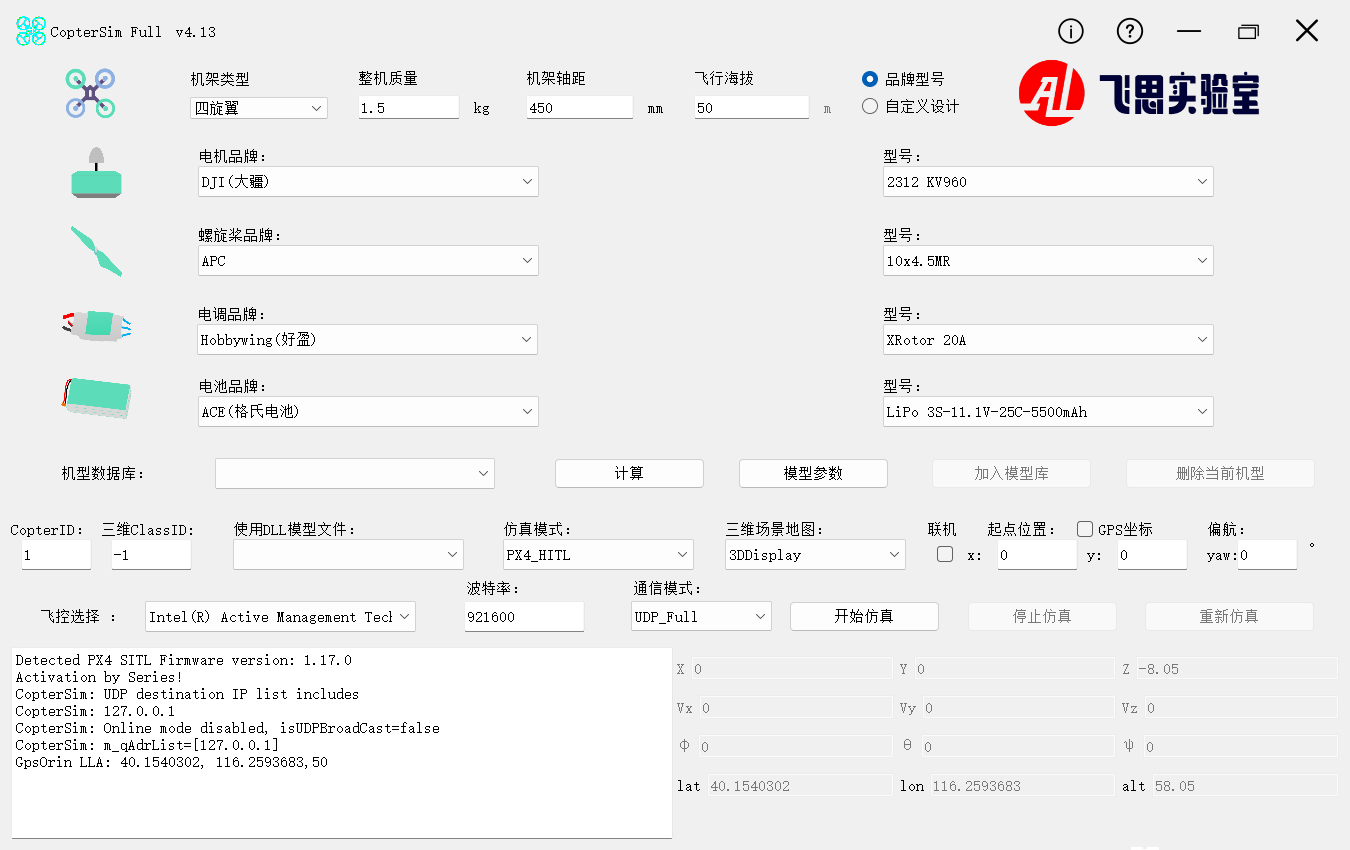
Model Configuration Area (Top)
This area is used to configure multirotor vehicle configuration and power system parameters, suitable for rapid modeling of standard multirotors.
Frame and Basic Parameters
| Parameter | Description |
|---|---|
| Frame Type | Trirotor / 3-axis 6-rotor / Quadrotor / Hexarotor / 4-axis 8-rotor / Octocopter |
| Total Mass | Unit: kg |
| Frame Wheelbase | Unit: mm |
| Flight Altitude | Unit: m |
| Input Mode | Brand/Model / Custom Design |
Power System Parameters
- Motor: KV value, no-load current/voltage, outer diameter, internal resistance, max continuous current
- Propeller: Outer diameter, pitch, number of blades
- ESC (Electronic Speed Controller): Continuous current, max voltage, internal resistance
- Battery: Nominal voltage, capacity, discharge rate, internal resistance
Brand/Model Mode
In Brand/Model mode, selecting a brand automatically populates the corresponding component parameters; switching to Custom Design mode allows manual input of all parameters.
Model Database Operations
| Control | Function |
|---|---|
| Model Database Dropdown | Select from built-in database ModelData.db |
| Confirm Model Parameters | Confirm parameters and enable calculation |
| Calculate | Compute hover time, throttle percentage, and other flight performance metrics |
| Add to Model Library | Save current configuration to database |
| Delete Current Model | Remove selected model from database |
Simulation Control Area (Middle)
| Function | Description |
|---|---|
| Simulation Mode | Select current simulation mode |
| DLL / XML Model | Select external flight model; choose “Default” to use built-in model |
| 3D Scene | Select 3D display map/scene |
| Vehicle ID | Set aircraft ID for current CopterSim instance |
| Takeoff Position | X / Y / Yaw |
| Connect | Enable UDP broadcast for multi-vehicle coordination or remote display |
| UDP Port / Target IP | Customize remote IP or port |
| GPS Coordinates | Interpret X/Y as latitude/longitude (Full Version+) |
| Autopilot Selection | Select Pixhawk serial port in HITL mode |
| Baud Rate | Default: 921600 (Full Version+ allows modification) |
| Communication Mode | Select data communication method |
| Start / Stop / Reset Simulation | Simulation control buttons |
Status Display Area (Bottom)
- Left: Log window displaying runtime logs, connection status, and error messages
- Right: Real-time status display, including position, velocity, attitude, and GPS
- Bottom Status Bar: Frequency monitoring for
SimHz / SensorHz / PwmHz / PosHz / OffHz / OdoHz
Model Database and FlyEval
CopterSim includes a built-in multirotor component database ModelData.db, containing parameters for commonly used components such as motors, propellers, ESCs, and batteries.
Additionally, the RflySim team provides the online evaluation tool FlyEval: https://flyeval.com
It can be used for:
- Rapid component selection and performance evaluation
- Automatic calculation of full-vehicle model parameters
- Exporting configuration files compatible with Simulink and CopterSim
CLI and Batch Execution
Command-Line Syntax
CopterSim supports startup via command-line arguments. The basic syntax is:
In practical usage, the first 11 parameters are typically the most critical, while the remaining parameters are used for auxiliary modes and extended settings.
Parameter List
| Parameter | Name | Description | Format / Values |
|---|---|---|---|
argv[1] |
isAutoStart |
Auto-start mode | 0=Manual, 1=Auto, >1=Auto + Real-time Preservation |
argv[2] |
copterID |
UAV ID | Numeric |
argv[3] |
uavType |
UAV type | 0=X-type quadcopter, 1=+type quadcopter |
argv[4] |
model |
Flight model | 0=Default, DLL filename, XML filename |
argv[5] |
simMode |
Simulation mode | Numeric or string name |
argv[6] |
mapName |
Map name | String or numeric index |
argv[7] |
udp |
UDP broadcast settings | 0, 1, IP list, json |
argv[8] |
posX |
Initial X coordinate (m) | Single UAV: numeric; Multi-UAV: semicolon-separated |
argv[9] |
posY |
Initial Y coordinate (m) | Same as above |
argv[10] |
yaw |
Initial yaw angle (°) | Same as above |
argv[11] |
com |
Serial port | COM3, 3, COM3:115200, 0=Auto |
argv[12] |
udpMode |
Communication mode | Numeric or string name |
argv[13] |
plusMode |
Auxiliary mode | Extension flags |
argv[14] |
altRollPitch |
Altitude / Attitude | alt;roll;pitch |
argv[15] |
gps |
Initial GPS | isPosGps;isBatLLAOrin;lat;lon;alt |
argv[16] |
autoLog |
Auto logging | 0=Disabled, 1=Enabled |
Common Examples
# PX4 Hardware-in-the-Loop (Basic)
CopterSim.exe 1 1 0 0 0 Grasslands 1

# PX4 SITL + MAVLink Communication
CopterSim.exe 1 1 0 0 2 Grasslands 1 0 0 0 1 Mavlink_Full

# Three-vehicle Simulation
CopterSim.exe 1 3 0 0 0 Grasslands 1 0;10;20 0;10;20 0;90;180

# Full Parameter Example
CopterSim.exe 1 1 0 0 1 Grasslands 1 0 0 0 COM3:115200 2 1 10;0;0 1;0;39.9;116.4;100 1
When to Prefer NoUI
CopterSimNoUI.exe is recommended in the following scenarios:
- Need to batch-launch a large number of instances.
- Need to automatically trigger experiments via BAT / scripts.
- GUI is unnecessary; only data interfaces and runtime efficiency matter.
- Limited single-machine resources; aim to reduce overhead from the graphical interface.
Multi-Vehicle and Networked Simulation
Position Array Format
In multi-vehicle simulation, argv[8] / argv[9] / argv[10] use semicolon-separated values, e.g.:
This indicates three vehicles starting at different positions and yaw angles.
Instance Limit
| Edition | Max Concurrent Instances |
|---|---|
| Free Edition | 8 |
| Full / Custom Edition | Unlimited |
Batch Launch Strategy
For large-scale multi-vehicle simulations, it is recommended to use CopterSimNoUI.exe with BAT scripts:
# 20 UAVs, using LowGPU scene to reduce resource consumption
CopterSimNoUI.exe 1 20 0 0 2 LowGPU 1 ...
Resource Optimization
NoUI + LowGPU is the most common combination for large-scale experiments, significantly reducing CPU and GPU usage.
UDP Broadcast and Network Communication
- Local Broadcast:
argv[7]=1, automatically adds127.0.0.1. - Specified Target IP:
argv[7]=IP address, multiple IPs separated by semicolons. - JSON Configuration:
argv[7]=json, usesexternal\json\Config.json, supported only inPX4_SITL_RFLYmode.
Communication Recommendations for Multi-Vehicle Scenarios
| Scenario | Recommendation |
|---|---|
| Small-scale multi-vehicle debugging | GUI + UDP_Full / Mavlink_Full |
| Large-scale multi-vehicle | NoUI + UDP_Simple |
| Multi-node network experiments | Configure target IP or JSON broadcast |
Flight Models and Configuration Methods
Three Model Loading Methods
| Method | Description |
|---|---|
| Built-in Default Model | Uses built-in quadrotor dynamics model, parameters configured via GUI |
| DLL Custom Model | Loads external DLL / SO model files |
| XML Configuration Model | Defines model physical parameters via XML |
Built-in Default Model
Suitable for rapid modeling of standard multirotors; users only need to configure frame, power system, and environmental parameters in the GUI.
DLL Custom Model
DLL models are generated by Simulink automatic code generation or written directly in C++, and are stored by default in:
Common built-in DLL models are as follows:
| File Name | Purpose |
|---|---|
FixWingModel |
Fixed-wing model |
CarAckerman |
Ackermann steering vehicle |
CarR1Diff |
Differential drive vehicle |
CarNoCtrl |
Uncontrolled vehicle |
MulticopterNoCtrl |
Uncontrolled multirotor |
MulticopterNOpx4 |
Multirotor without flight controller |
CopterSILVelCtrl |
Velocity-controlled multirotor SIL |
MultSILSwarm |
Multi-vehicle swarm SIL |
Trailer |
Trailer model |
Exp1_MinModelTemp |
Minimum model template |
Exp2_MaxModelTemp |
Maximum model template |
XML Configuration File
XML model configuration files are stored by default in:
The main parameter groups are as follows:
| Parameter Group | Included Fields |
|---|---|
ModelInfo |
Mass, gravitational acceleration, moment of inertia, fuselage radius, thrust coefficient, torque coefficient, motor response time, air resistance coefficient, etc. |
HoverInfo |
Hover time, throttle percentage, motor current / RPM / power, energy efficiency |
FrameInfo |
Number of rotors, number of arms, configuration, noise level |
ClassID |
3D model ClassID (-1=Auto) |
Model Development and Import Process
Development Process Overview

The common process for integrating a custom model into CopterSim is:

Simulink Modeling Template
RflySim provides standard Simulink modeling templates, with core interfaces including:
| Channel Name | Direction | Description |
|---|---|---|
inPWMs |
Input | Motor control inputs from the autopilot |
TerrainIn15d |
Input | Terrain data from CopterSim or the 3D simulator |
HILSensor30d |
Output | Sensor data fed back to the autopilot |
HILGPS30d |
Output | GNSS positioning data fed back to the autopilot |
VehicleInfo60d |
Output | Simulation status sent to the 3D simulator |
Auxiliary extension interfaces include:
| Channel Name | Description |
|---|---|
inCollision20d |
Collision feedback from the 3D simulator |
inSIL28d |
External control and fault trigger signals |
inCopterData |
Flags such as flight controller arming status and vehicle type |
outCopterData |
Key model state outputs, writable to logs |
ExtToPX4 |
Model-side data directly sent to the autopilot |
ExtToUE4 |
Trigger signals sent to the 3D simulator |
Interface Consistency
When developing models, you must strictly adhere to the interface names and communication protocols; otherwise, CopterSim will fail to correctly recognize and drive the model.
DLL Compilation and Import Steps
- Complete model development in Simulink and connect it to the standard interfaces.
- Use Simulink Coder to generate C/C++ code.
- Compile the generated code into a DLL (Windows) or SO (Linux).
- Place the generated files into the
external\model\directory. - Launch CopterSim and load the corresponding model in the model configuration area.
Detailed procedures can be referenced in:
Multirotor DLL-Free Operation
For standard multirotor vehicles, models can often be generated directly via GUI parameter configuration without requiring separate DLL development.
Integrated Modeling Approach
Beyond the standard "motion model + PX4 controller" mode, RflySim also supports an integrated modeling approach:
- Integrate control algorithms directly within the Simulink motion model.
- The generated DLL possesses autonomous control capability and no longer relies on PX4.
- Particularly suitable for large-scale swarm simulations and reinforcement learning-accelerated training.
Key Modeling Considerations for Typical Vehicles

| Vehicle Type | Control Inputs | Modeling Highlights | Reference Example |
|---|---|---|---|
| Multirotor | 4–8 throttle channels | Layout and thrust synthesis matrix | e2_MultiModelCtrl/Readme.pdf |
| Fixed-wing | Throttle + elevator + aileron + rudder | Aerodynamic coefficients and coordinated turns | e3_FWingModelCtrl/Readme.pdf |
| VTOL (Compound) | Rotors + control surfaces (dual channels) | Hover/cruise mode transition | e4_VTOLModelCtrl/Readme.pdf |
| Differential Drive UGV | Left/right wheel speeds | Wheelbase and slip compensation | e6_CarR1DiffCtrl/Readme.pdf |
| Ackermann Steering UGV | Throttle + steering angle | Front-wheel steering geometry | e5_CarAckermanCtrl/Readme.pdf |
Modeling Philosophy and Motion Simulation Framework
Model-Based Design (MBD)
The design of CopterSim deeply embodies the Model-Based Design (MBD) philosophy. The core idea of MBD is not "write code first, then verify," but rather to first build models, conduct simulations, and perform closed-loop validation early on, gradually progressing toward code generation and hardware deployment.

MBD Six-Stage Workflow
| Stage | Content | Role of CopterSim |
|---|---|---|
| ① Modeling & Identification | Construct high-fidelity dynamic models | Provides model configuration and motion simulation support |
| ② Rapid Control Prototyping | Build controller prototypes | Supports early-stage controller integration and tuning |
| ③ Digital Simulation Validation | Simulink closed-loop simulation | Supports DLL model import and execution |
| ④ Automatic Code Generation | Model → C/C++ → DLL | Loads auto-generated code |
| ⑤ Hardware-in-the-Loop (HITL) Simulation | Connect to real autopilots | Acts as serial/network master node |
| ⑥ System Integration Testing | Real-vehicle deployment and validation | Serves as the bridge between simulation and real-world deployment |
Closed-Loop Validation
The significance of CopterSim lies not only in "making things fly," but more importantly in supporting a continuous validation chain—from pure models, through autopilot integration, to HITL, and finally to real-vehicle migration.
Unified Modeling Framework

The motion model of unmanned vehicle systems consists primarily of three subsystems:
| Subsystem | Function | Key Outputs |
|---|---|---|
| Vehicle Body Subsystem \(S_\text{vehi}\) | Models evolution of position, velocity, attitude, and angular velocity | Pose, velocity, angular velocity |
| Sensor Subsystem \(S_\text{sens}\) | Simulates IMU, GPS, magnetometer, etc. | Raw or noisy sensor outputs |
| 3D Environment Subsystem \(S_\text{3d}\) | Provides visual environment, terrain, and sensor environment | Images, point clouds, terrain feedback |
Together with the control subsystem \(S_\text{ctrl}\), they form a complete closed-loop system.
Vehicle Body Subsystem

The vehicle body subsystem primarily comprises four layers:
- Body Module: Describes translational and rotational motion using a six-degree-of-freedom rigid-body equation.
- Environment Module: Models atmosphere, gravity, wind fields, magnetic fields, and terrain.
- Actuator Module: Models static and dynamic responses of actuators such as motors and propellers.
- Force and Torque Module: Synthesizes gravitational force, aerodynamic force, contact force, and actuator control force.
Multirotor Thrust and Torque Synthesis
For multirotors, the thrust and counter-torques of individual propellers are synthesized into total thrust and three-axis torques via a control efficiency matrix. This matrix is determined by the number of rotors, their spatial distribution, and rotation directions.
Sensor Subsystem
Sensor modeling typically consists of three layers:
- Ideal Data Layer: Extracts ideal sensor outputs from ground-truth states.
- Product Characteristics Layer: Adds noise, drift, and calibration errors.
- Interface Packaging Layer: Packages data according to protocols such as MAVLink before sending to the autopilot.
In HITL mode, CopterSim sends sensor data to PX4 via the HIL_SENSOR and HIL_GPS messages.
Performance Tuning and Troubleshooting
Common Issues and Solutions
| Issue | Possible Cause | Solution |
|---|---|---|
| Serial port connection failure | COM port occupied or incorrect format | Check Device Manager to confirm serial port number and baud rate |
| EKF crash and restart | Autopilot EKF initialization anomaly | Re-power the autopilot; reconnect hardware if necessary |
| Heartbeat packet loss | Autopilot fails to respond to MAVLink properly | Check serial port, firmware, and connection status |
| Low simulation frequency (<100Hz) | Insufficient system performance | Prefer NoUI mode and close background processes |
| Free version feature limitations | Version restrictions | Switch to the full or customized version |
| GPS coordinates unavailable | Free version does not support advanced coordinate settings | Use default coordinates or upgrade the version |
| Vehicle jitter | Model parameter mismatch or PID not tuned | Re-calibrate model parameters and adjust control parameters using QGC |
| Slow SITL startup | WSL environment anomaly | Confirm WSL runs normally and disable antivirus software interference |
| Multi-vehicle stuttering | Excessive rendering load | Use LowGPU scene or distributed deployment |
Performance Optimization Recommendations
- Prefer
CopterSimNoUI.exefor multi-vehicle scenarios. - Use
LowGPUor lighter scenes to reduce rendering overhead. - Deploy CopterSim and RflySim3D on separate computers.
- For cluster experiments, prefer
UDP_Simpleto reduce bandwidth usage. - Disable automatic logging during large-scale experiments to reduce disk I/O.
High-Precision Timing
CopterSim automatically enables high-precision timers and disables system-level power-saving and frequency-throttling features to maximize simulation frequency stability.
File Locations and Related Resources
Common Directories
Installation Directory     %PSP_PATH%\CopterSim\
Model Directory            %PSP_PATH%\CopterSim\external\model\
XML Configuration          %PSP_PATH%\CopterSim\external\XML\
Map Files                  %PSP_PATH%\CopterSim\external\map\
JSON Configuration         %PSP_PATH%\CopterSim\external\json\
Log Files                  %PSP_PATH%\CopterSim\Log\
Model Database             %PSP_PATH%\CopterSim\ModelData.db
Recommended Further Reading
- RflySim3D
- QGroundControl
- [RflySim Installation Path]\RflySimAPIs\4.RflySimModel\1.BasicExps\e0_MinModelTemp
- [RflySim Installation Path]\RflySimAPIs\5.RflySimFlyCtrl\0.ApiExps\17.OffboardCtrlsAPI
Note: This page has been restructured to prioritize "first understand the positioning, then master the modes and operations, and finally delve into models and principles." If your goal is to run experiments, it is recommended to focus on the "Simulation Modes," "Communication Modes," "GUI and CLI," and "Multi-Vehicle and Model Import" sections.