vrpn_data_decoder Module Documentation
Toolbox: RflySim Swarm
Introduction
One-sentence Description: Parses and decodes VRPN motion-capture data received by the
RflyVrpnRecvmodule, outputting various drone state information in bus format.
This module serves as the core component for processing motion-capture positioning data within the RflySim Swarm cluster toolchain. It is designed to be used in conjunction with the RflyVrpnRecv data reception module, primarily to parse raw data packets transmitted via the VRPN protocol from external motion-capture systems into structured data directly usable for simulation and control. In applications such as cluster cooperative positioning, indoor drone control simulation, and motion-capture-assisted state estimation, this module acts as a critical intermediate layer connecting the motion-capture system with Simulink-based control algorithms.
Upon completion of parsing, the module outputs the drone’s motion-capture position, velocity, acceleration, and timestamp in bus format. It also outputs a validity flag for the received data, enabling control logic to assess data availability. When extracting data from the bus, MATLAB automatically prompts the available data items contained in the bus, facilitating rapid integration of user-designed control algorithms. The processed data can further be integrated with CopterSim, PX4 firmware, and RflySim3D to achieve closed-loop simulation and 3D visualization.
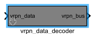
Port Descriptions
Input Ports (Inputs)
| Port Name | Data Type | Dimension | Description |
|---|---|---|---|
RawData |
double |
N×1 |
Raw VRPN data output by the RflyVrpnRecv module |
Output Ports (Outputs)
| Port Name | Data Type | Dimension | Description |
|---|---|---|---|
StateBus |
Bus |
1 | Bus signal containing various drone state information |
ValidFlag |
boolean |
1×1 | Flag indicating whether valid VRPN data has been received: 1 = valid, 0 = invalid |
Parameter Configuration (Parameters)
The following parameters can be configured in the Mask dialog box opened by double-clicking the module:
| Parameter Name | Type | Default Value | Optional Values / Range | Description |
|---|---|---|---|---|
UAVName |
string |
"Quad1" |
- | Name of the target drone for VRPN data decoding [to be confirmed] |
Parameter Setting Description
UAVName
Specifies the VRPN data name of the target drone to be decoded. The module extracts the state information of the drone with the specified name from the raw data output by RflyVrpnRecv and outputs it to the bus.
Module Characteristics (Block Characteristics)
| Characteristic | Value |
|---|---|
| Supported Data Types | double, single |
| Direct Feedthrough | Yes |
| Sample Time | Inherited |
| Code Generation Support | No |
Data Communication Protocol
This module does not involve network communication.
Related Modules
| Module Name | Description |
|---|---|
RflyVrpnRecv |
Receives raw data from the VRPN motion-capture system and serves as the input source for this module |
UAV_Dynamics_4Rfly |
Accepts the drone state data output by this module for swarm simulation validation |
PX4_Simulink_Control |
Enables closed-loop control based on the motion-capture state information output by this module |
Notes and Common Issues
- Initialization Sequence: This module must be used in conjunction with the
RflyVrpnRecvmodule from the same library. Before running the simulation, ensure that theRflyVrpnRecvmodule is correctly configured and connected to this module’s input port; otherwise, bus data type mismatches or zero-output errors may occur. - Sample Time Matching: The sample time of this module must match the receiving sample time of the upstream
RflyVrpnRecvmodule. Excessive sample time differences may cause state data jumps and non-continuous timestamps. It is recommended to set both to the same discrete sample time. - Bus Data Extraction: When using the Bus To Element module to extract data from the bus, if the corresponding signal cannot be found, check whether the corresponding bus object has been generated in the MATLAB workspace after simulation starts, or reconnect the extraction module after updating the bus data definition.
- Validity Flag Usage: The
ValidFlagoutput by this module serves as the basis for determining data validity. When developing control logic, it is recommended to include a check for this flag to avoid using outdated or erroneous historical state data when motion-capture data is lost, which could lead to simulation anomalies. - Multi-UAV Cluster Scenarios: In cluster simulations, each drone requires its own dedicated
vrpn_data_decodermodule. Do not share a single decoder module among multiple drones, as this may cause data crosstalk or decoding errors.
Changelog
v4.0.0(2024-01-01): Initial release. Introduced thevrpn_data_decodermodule, supporting decoding of drone motion-capture position, velocity, acceleration, timestamp, and data validity flag in conjunction withRflyVrpnRecv, outputting various state information via bus format.