HIL16CtrlsPWM Module Documentation
Toolbox: RflySim APIs
Introduction
One-sentence Description: For hardware-in-the-loop (HIL) simulation, this module transmits 16 channels of PWM control signals generated by Simulink to CopterSim, while supporting automatic switching and configuration of PX4 modes and outputs.
This module belongs to the RflySim APIs library and is specifically designed for drone hardware-in-the-loop (HIL) simulation development. It enables users to design custom controllers in Simulink and directly integrate their control outputs into CopterSim’s dynamics simulation pipeline. Through parameter configuration, the module supports features such as automatic arming, PX4 output blocking, and automatic mode switching. When the Simulink controller is enabled, it injects custom control outputs; when disabled, it automatically switches PX4 to Loiter mode to maintain drone hover—making it highly suitable for HIL validation and development of custom flight control algorithms.
The module transmits normalized 16-channel PWM control signals to the dynamics DLL model input port of CopterSim via API interfaces, accommodating control signal mapping requirements for various drone configurations (e.g., multirotors, fixed-wings). Combined with the PX4 flight controller and RflySim3D visualization module, it enables a complete HIL simulation workflow—from algorithm design to simulation validation.
Port Descriptions
Input Ports
| Port Name | Data Type | Dimension | Description |
|---|---|---|---|
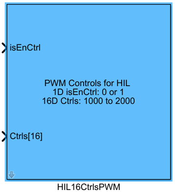
isEnCtrl |
double |
1×1 |
Control signal enable flag: when input is true, control data from the CtrlS[16] port is transmitted; when false, full 1000 control signals are sent |
CtrlS |
double |
1×16 |
16-dimensional PWM control signals, ranging from 1000 to 2000, used for hardware-in-the-loop simulation |
Output Ports
This module has no output ports.
Parameter Configuration
The following parameters can be configured in the Mask dialog box opened by double-clicking the module:
| Parameter Name | Type | Default Value | Available Values/Range | Description |
|---|---|---|---|---|
Auto arm |
bool |
false |
true/false |
Automatic arming switch: when enabled, the module automatically sends an arming command when isEnCtrl is true |
Auto block PX4 |
bool |
false |
true/false |
PX4 output blocking switch: when enabled, the module blocks PX4 output and uses the Simulink controller to drive the vehicle when isEnCtrl is true |
Auto Loiter |
bool |
false |
true/false |
Automatic Loiter mode switch: when enabled, the module unblocks PX4 output and switches PX4 to Loiter mode when isEnCtrl is false, ensuring the vehicle remains hovering under PX4 control |
Sample Time(s) |
double |
0.01 |
> 0 | Module sample time in seconds |
Parameter Setting Notes
Auto arm
When enabled, the module automatically sends an arming command to the flight controller upon control enablement (isEnCtrl = true), eliminating the need for manual arming—ideal for automated simulation workflows.
Auto block PX4
This parameter enables the Simulink custom controller to override the flight controller’s output. When enabled, the native PX4 controller’s output is blocked during custom control enablement, and the vehicle is driven by the CtrlS control signals generated by the Simulink model.
Auto Loiter
This parameter ensures simulation safety: when custom control is disabled (isEnCtrl = false), the module automatically switches the flight controller to Loiter mode, allowing PX4 to maintain drone hover and prevent loss of control during simulation.
Sample Time(s)
This parameter aligns with the flight controller’s control cycle. For multirotor simulations, it is typically set to 0.01 s (corresponding to a 100 Hz control frequency), and should be adjusted according to the actual sampling period of the custom controller.
Module Characteristics
| Characteristic | Value |
|---|---|
| Supported Data Types | double, single |
| Direct Feedthrough | Yes |
| Sample Time | Discrete |
| Code Generation Support | No |
Data Communication Protocol
This module transmits 16-channel PWM control data to CopterSim via UDP, with the default target port set to 2010. Each data packet consists of 17 consecutive double-type values: the first is the control enable flag isEnCtrl, followed by 16 PWM control signals CtrlS[16]. Each value occupies 8 bytes, resulting in a total packet size of 136 bytes.
Related Modules
| Module Name | Description |
|---|---|
PWM_output |
Outputs multiple motor PWM control signals for hardware-in-the-loop simulation |
HILActuatorFeedBack |
Reads actuator (servo/motor) status feedback from CopterSim |
VehicleStateGet |
Reads complete vehicle state information output by CopterSim |
SetVehiclePos |
Sends commands to set the initial position of the drone in CopterSim |
Usage Example
For related usage examples, refer to the following path:
Please refer to
Readme.pdfin the path above for complete example descriptions and operational steps.
Notes and Common Issues
- Initialization Sequence: This module requires CopterSim to complete initialization before it can send control signals normally. It is essential to ensure that CopterSim has finished model loading and port connection before starting the Simulink simulation; otherwise, control signal transmission may fail.
- Sample Time Matching: The module’s
Sample Time(s)parameter must match the simulation step size configured in CopterSim. Mismatched sample times will cause asynchronous control signal transmission, leading to unstable drone attitude during simulation. - Input Signal Range: The 16-dimensional PWM control signal
CtrlS[16]must remain within the range of 1000–2000. Values outside this range will cause normalization conversion errors on the CopterSim side, resulting in abnormal motor output. Note that the normalization mapping rules differ between multirotor and fixed-wing models: for multirotors, 1000–2000 maps to an output of 0–1, while for fixed-wings, 1000–2000 maps to an output of -1–1. Adjust input ranges accordingly based on the vehicle type during development. - Mode Switching Logic: If both
Auto LoiterandAuto block PX4are enabled, ensure the logic of theisEnCtrlport is correct: whenisEnCtrlisfalse, PX4 will automatically switch to Loiter mode for hovering; before switching back to Simulink control, verify that the vehicle’s state is stable to prevent attitude loss of control during the transition. - Port Enable Logic: When the
isEnCtrlinput isfalse, the module defaults to sending control signals with all values set to 1000. For multirotor models, this corresponds to zero throttle output. Confirm that the enable logic aligns with design requirements before simulation to avoid unintended altitude loss.
Changelog
v4.20(2024-08-07): Initial release. Supports sending hardware-in-the-loop, 16-dimensional normalized PWM control signals to CopterSim, and provides features including automatic arming, PX4 output blocking, and automatic Loiter mode configuration.