AUX_output Module Documentation
Toolbox: Sensors and Actuators
Introduction
One-sentence Description: This module sends custom PWM control signals to the PX4 FMU auxiliary output ports, enabling the drive of various auxiliary actuators.
This module belongs to the Sensors and Actuators interface library of the RflySim toolchain. It serves as an auxiliary extension to the main PWM output module, specifically designed to meet the drive requirements of non-flight-control-type actuators in UAV simulation systems. Typical use cases include simulating control of auxiliary devices mounted on UAVs, such as servos, camera gimbals, and payload release mechanisms, supporting developers in defining custom action logic for auxiliary devices. The module works in conjunction with CopterSim and the PX4 simulation firmware to transmit PWM control signals generated in Simulink to PX4, thereby driving the simulation of auxiliary devices. Ultimately, it can be integrated with RflySim3D to achieve 3D visualization of auxiliary device actions, or directly reused in actual hardware-based PX4 flight control systems.
Port Descriptions
Input Ports (Inputs)
| Port Name | Data Type | Dimension | Description |
|---|---|---|---|
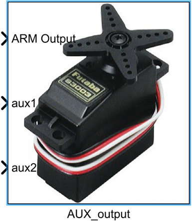
ARM Output |
boolean |
1×1 |
Enables or disables PWM signal output on the FMU ports |
PWM signals |
uint16 |
N×1 or 1×N |
Each input signal corresponds to a selected FMU auxiliary port, used to control connected auxiliary devices; N is the number of selected PWM ports |
Output Ports (Outputs)
This module has no output ports.
Parameter Configuration (Parameters)
The following parameters can be configured in the Mask dialog box opened by double-clicking the module:
| Parameter Name | Type | Default Value | Available Values / Range | Description |
|---|---|---|---|---|
PWM Update Rate |
enum |
50Hz |
50Hz, 125Hz, 250Hz, 300Hz, 400Hz | Sets the update frequency of the PWM signal, i.e., the refresh rate of auxiliary device control signals |
PWM Port Selection |
multiselect |
None | Ports 1 ~ 6 | Selects the PX4 FMU auxiliary PWM ports to output PWM signals; up to 6 ports can be selected |
Parameter Setting Notes
PWM Update Rate
Different auxiliary devices typically require different PWM update rates—for example, conventional servos generally use a 50Hz update rate, while high-speed servos require higher rates. Users should select a matching update rate based on the specifications of the actual devices being used.
PWM Port Selection
This parameter selects the PX4 hardware FMU auxiliary PWM ports to output PWM signals. The number of selected ports determines how many PWM input signals the module expects, with port order corresponding one-to-one with input signal order.
Module Characteristics (Block Characteristics)
| Characteristic | Value |
|---|---|
| Supported Data Types | double, single, uint16, boolean |
| Direct Feedthrough | Yes |
| Sample Time | Discrete |
| Code Generation Support | No |
Data Communication Protocol
This module communicates with the PX4 flight control simulation environment via the MAVLink protocol, sending PWM output commands to the corresponding auxiliary ports of the flight controller. Data transmission uses the default flight control communication UDP port configured in the RflySim platform.
Related Modules
| Module Name | Description |
|---|---|
PWM_output |
Main PWM output module, used to control primary propulsion actuators of the UAV |
ESC_Calibration |
ESC calibration module, used for zero-point calibration of PWM-driven ESCs |
Usage Example
Refer to the following path for related usage examples:
Please refer to
Readme.pdfin the above path for complete example descriptions and operational steps.
Notes and Common Issues
- Initialization Sequence: This module relies on the RflySim simulation environment and the PX4 flight control low-level drivers for initialization. The module must be placed inside an enabled subsystem in the Simulink model to ensure that the PX4 flight control connection and initialization are completed before enabling PWM output, preventing unresponsive outputs due to initialization anomalies.
- Port Correspondence: The 6 selectable PWM ports correspond to the physical AUX PWM output pins of the PX4 FMU and must match the AUX output port mapping configured in the PX4 firmware. If no output is observed, verify the SERVO_OUTPUT_FUNCTION parameter settings in the PX4 firmware to ensure correct port function assignments.
- PWM Update Rate Matching: Strictly set the PWM update rate according to the specifications in the connected auxiliary device’s manual—for example, standard analog servos must be set to 50Hz. Mismatched update rates may cause servo jitter, insufficient control accuracy, or even device damage.
- Input Data Range: PWM signal inputs are of type
uint16. The standard valid control range for conventional PWM servos is typically 1000–2000 μs; input values outside this range may not be recognized by the device. Avoid entering values beyond the hardware-supported range. - Output Enable Logic: PWM signal output on AUX ports is enabled only when the
ARM Outputinput is true (boolean value 1). If no output is observed after simulation starts, first check whether this input signal is functioning normally. - Sample Time Matching: The module’s PWM refresh rate is controlled by the
PWM Update Rateparameter. It is recommended to set the sample time of the simulation task containing this module to no more than half the PWM update period, ensuring proper signal refresh and avoiding update delays. - Difference from Main PWM Output Module: This module is exclusively for PWM output on PX4 AUX auxiliary channels. Do not map the same physical output port concurrently with the main PWM output module to avoid port conflicts and abnormal outputs.
Changelog
v4.10(2024-08-12): Added the AUX_output auxiliary PWM output module, supporting PWM signal transmission to PX4 FMU auxiliary output ports for driving auxiliary actuators such as servos and camera gimbals. Supports configurable PWM update rate and up to 6 auxiliary PWM outputs.