AT9S Pro
Loongson AT9S Pro 
1. Product Introduction
The AT9S Pro is a 12-channel transmitter supporting dual hybrid spread spectrum: 2.4G DSSS and FHSS, with 16-channel pseudo-random frequency hopping.
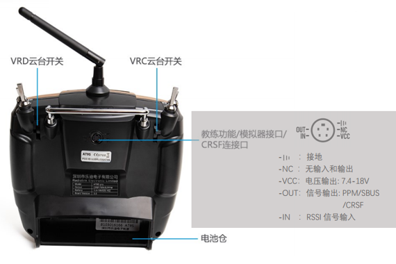
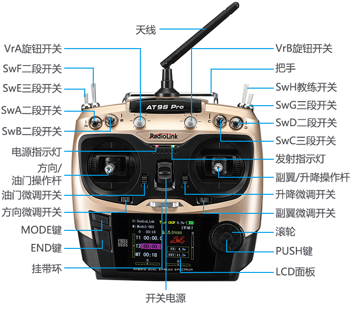
The transmitter hardware is illustrated below.
- Note: The Loongson AT9S Pro transmitter is primarily intended for indoor course experiments and is relatively low-cost.
2. Transmitter Configuration
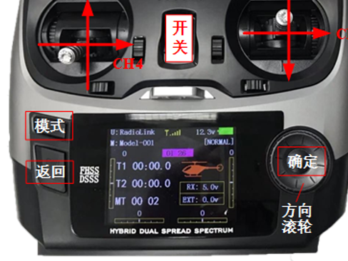
1) Flip the “switch” upward to power on the transmitter
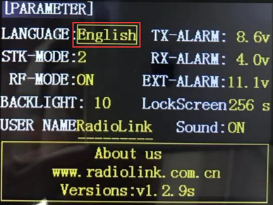
2) Set language to Chinese and disable sound
- · Long press the “MODE” button on the transmitter’s control panel,
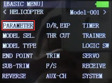
- · The model setup page shown in the left image below appears.
- · Rotate the “direction wheel” on the transmitter,
- · Move the cursor to “PARAMETER” in the figure above,
- · Press the “OK” button on the right side of the transmitter panel to enter the transmitter parameter setup page,
- · Rotate the “direction wheel” on the transmitter panel to select the “English” entry.
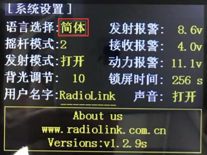
- · Press the “OK” button on the transmitter,
- · Then rotate the “direction wheel”,
- · Change the language to “Simplified” as shown in the figure below,
- · Then press the “OK” button to set the language to Chinese.
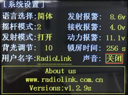
- · Using the same method, adjust the sound option from “ON” to “OFF” as shown in the figure.
3) Multirotor Mode Setup
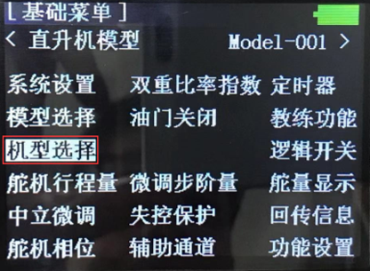
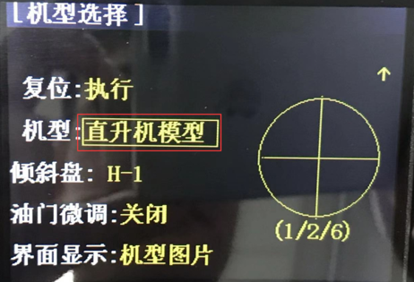
- · Long press the “MODE” button on the transmitter panel to enter the “Basic Menu” setup interface shown above, then select “Model Type” to enter the model selection page shown above.
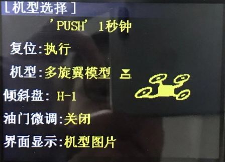
- · In the “Model Type” entry, change “Helicopter Model” to “Multirotor Model”, then long press the “OK” button on the transmitter panel for more than one second, as shown above, to set the transmitter mode to multirotor.
4) Throttle Channel Reversal Setup
- · In multirotor mode, the throttle channel of the Loongson transmitter is opposite to that defined by Pixhawk; therefore, adjustment is required.
- · Long press the “MODE” button on the transmitter panel,
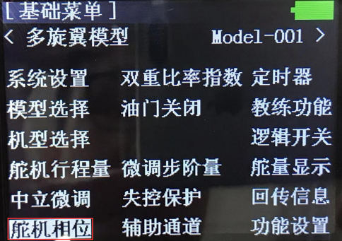
- · Enter the “Basic Menu” setup interface shown above and select the “Servo Phase” entry.
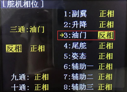
- · In the “Servo Phase” setup page, change the throttle from “Normal Phase” to “Reverse Phase”.
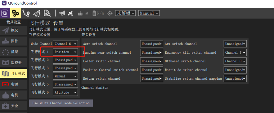
5) CH5 Mode Switch Channel Setup
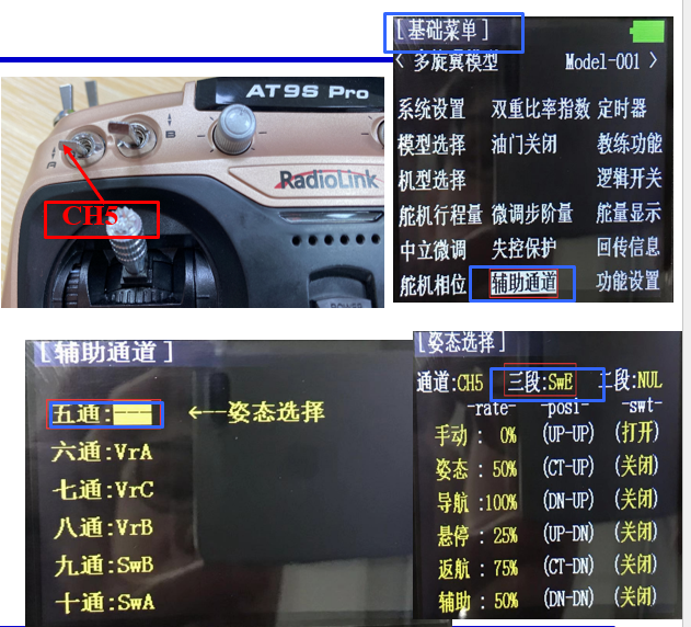
- · Due to experimental requirements, the fifth channel (CH5) of the transmitter must be mapped to the three-position toggle switch in the upper-left corner for controller mode switching.
- · Long press the “MODE” button on the transmitter panel to enter the “Basic Menu” setup interface shown above, then enter the “Auxiliary Channels” entry.
- · As shown in the figure above, enter the “5CH” setup page and map CH5 to the three-position switch “SwE” (the left upper front-panel switch “E”) on the transmitter. Similarly, map CH6 to “SwG”.
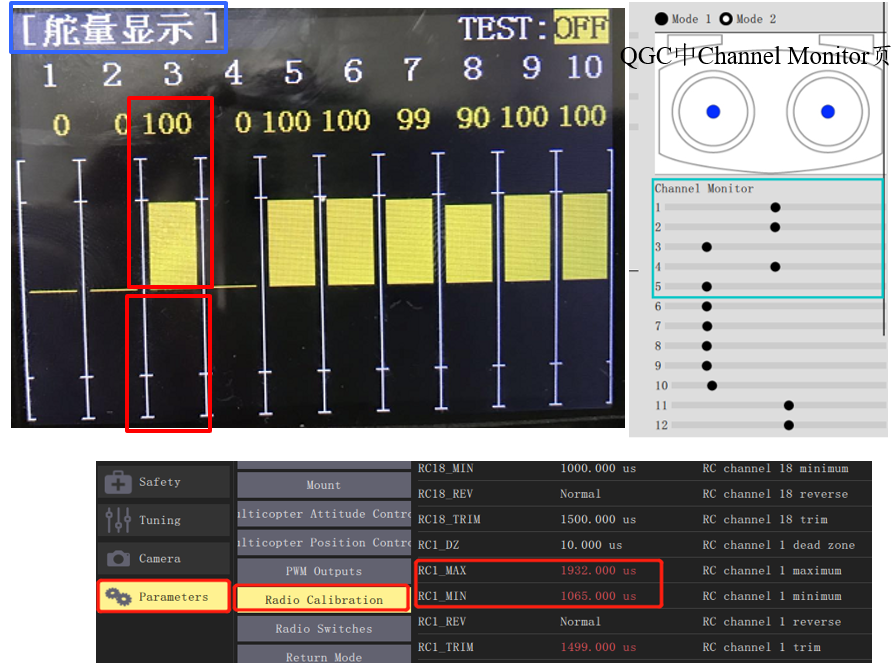
6) Channel Verification
- · On the main screen, press the “Back” button on the transmitter to display the “Servo Output” interface shown below. At this point, moving each joystick will show the corresponding PWM value changes for each channel.
Note: In the interface shown below, the upper “100” in the yellow region corresponds to a PWM value of 1100 (the corresponding channel slider in QGC’s Channel Monitor is at the leftmost position), and the lower “100” corresponds to a PWM value of 1900 (the corresponding channel slider in QGC’s Channel Monitor is at the rightmost position).
Due to various tolerances, the actual PWM signal received by the autopilot does not precisely match the 1100–1900 range; for example, the Loongson transmitter’s typical range is 1065–1933 (which can be verified in QGC under – Parameters – Radio Calibration page, as shown in the lower-right figure).
Therefore, transmitter calibration is essential for the autopilot to correctly interpret flight control commands sent from the transmitter. Transmitter calibration can be performed in the Radio page of the QGC ground station.
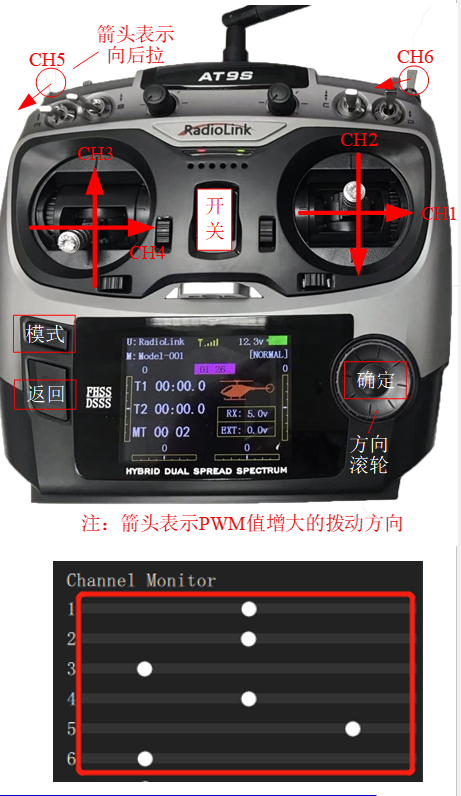
- · Move each joystick sequentially to verify that the channels are correctly defined as follows:
CH1: Roll control, corresponding to PWM values from 1100 (left) to 1900 (right) (QGC Channel Monitor slider #1 moves from left to right).
CH2: Pitch control, corresponding to PWM values from 1100 (top) to 1900 (bottom) (QGC Channel Monitor slider #2 moves from left to right).
CH3: Throttle control, corresponding to PWM values from 1900 (top) to 1100 (bottom) (note: this is opposite to CH2; QGC slider #3 moves from right to left).
CH4: Yaw control, corresponding to PWM values from 1100 (left) to 1900 (right).
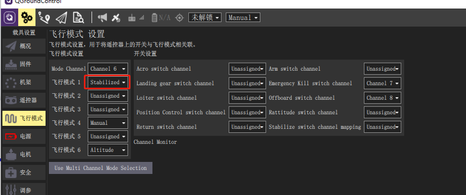
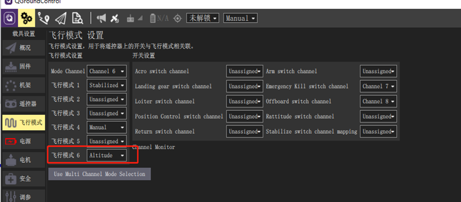
CH5/6: Mode control, via the SwE switch (upper-leftmost). This is a three-position toggle switch; the top position (farthest from the user), middle, and bottom (closest to the user) positions correspond to PWM values of 1100, 1500, and 1900, respectively.
7) Hardware Connections
For this simulation experiment, the preferred transmitter is the Loongson AT9S Pro transmitter paired with the matching R9DS receiver.
Required accessories include: a battery (LiPo, 3S, 11.1V) and matching charger to power the transmitter; a JR cable (or Dupont wires as an alternative) to connect the receiver to the Pixhawk autopilot; and a MicroUSB data cable to connect the Pixhawk autopilot to the computer.
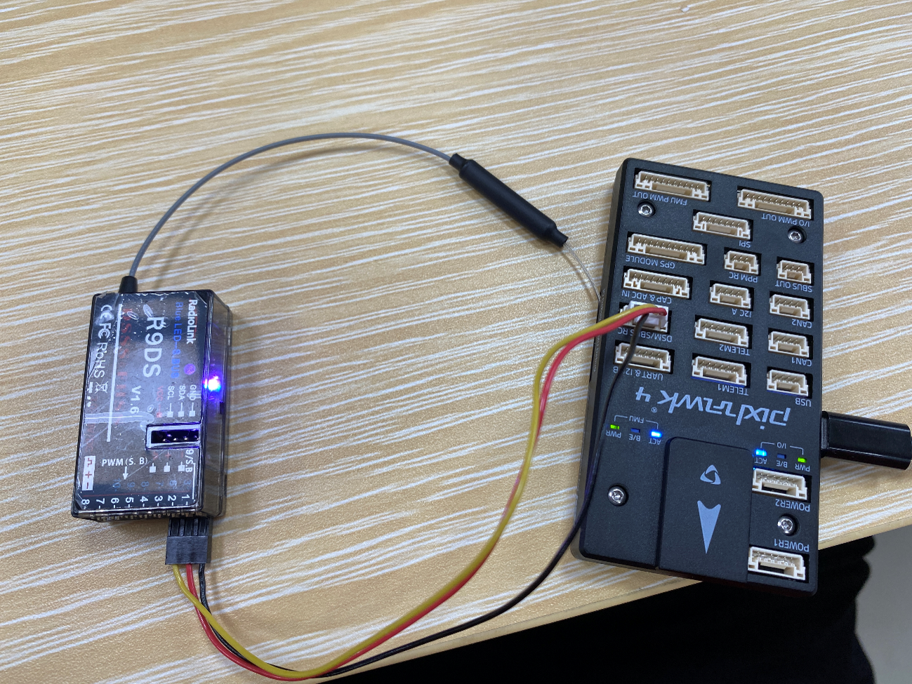
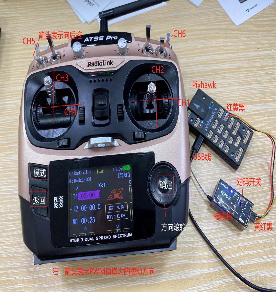
- · Connect according to the wiring diagram above: connect the receiver’s bottom-right pin header to the leftmost pin header of the flight controller via the JR cable (note the pin sequence—the receiver’s LED turns dark red if the cable is reversed). Connect the USB port to the computer’s USB port to power the receiver.
- · Re-pair the remote controller (by default, pairing is already completed; re-pairing is only required if connection issues occur). Turn on the remote controller’s power, then use a pen tip to press and hold the button on the right side of the receiver for more than one second. The LED will begin flashing, indicating it is searching for the nearest remote controller (ensure other remote controllers are turned off), and pairing begins. After flashing 7–8 times, the LED becomes steadily lit, indicating successful pairing and establishing a connection between the remote controller and the receiver.
- · S.BUS signal mode selection: S.BUS mode enables transmission of all channel PWM signals through a single JR cable, thereby establishing the connection between the receiver and the flight controller. If the LED is bluish-white, the receiver is already in S.BUS mode and no further configuration is needed. If the LED is red, press the button on the right side of the receiver twice within one second; when the LED turns bluish-white, S.BUS mode has been successfully switched.
- · Verify correct connection between the remote controller and receiver:
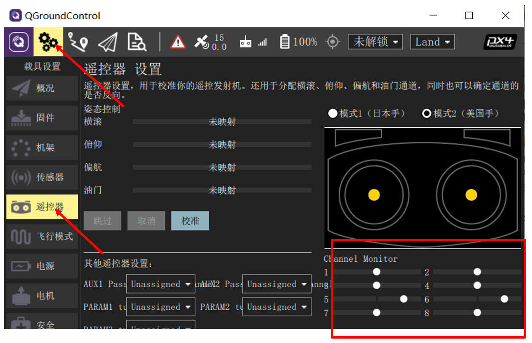
- Connect the autopilot to the receiver, then connect the autopilot to the computer using a USB data cable. Turn on the remote controller and open the QGroundControl ground station software.
- After QGroundControl successfully connects to the Pixhawk, click the “gear” button as shown in
In Stabilize mode, the multirotor drone stabilizes itself when the remote control sticks are centered. To manually move or fly the aircraft, you can displace the sticks from their centered positions.
Under manual control, the roll and pitch sticks control the aircraft’s angular orientation (attitude) around their respective axes, the yaw stick controls the rotation rate above the horizontal plane, and the throttle stick controls altitude/speed.
Once the sticks are released, they return to the center dead zone. When the roll and pitch sticks are centered, the multirotor will level out and cease motion. The aircraft will then hover in place/maintain altitude—provided it is properly balanced, the throttle is set appropriately (see below), and no external forces (e.g., wind) are applied. The aircraft will drift downwind, and you must adjust the throttle to maintain altitude.
2. Stabilize Mode (Fixed-Wing)
In Stabilize mode, when the sticks are centered, the aircraft enters straight and level flight, maintaining a level attitude and resisting wind (but not heading or altitude).
If the roll/pitch sticks are not zeroed, the drone climbs or descends according to pitch input and executes coordinated turns. Roll and pitch are angle-controlled (no looping or inverted flight possible).
If throttle is reduced to 0% (motors stop), the aircraft will glide. To execute a turn, the control command must be maintained throughout the maneuver, as releasing the roll stick causes the aircraft to stop turning and automatically level (likewise for pitch and yaw commands).
Note: Stabilize mode makes it easy to keep the aircraft level simply by centering the sticks.
3. Altitude Hold Mode (Multirotor)
Altitude Hold mode is a relatively easy-to-fly manual mode: roll and pitch sticks control the aircraft’s movement left/right and forward/backward (relative to the aircraft’s “forward” direction), yaw stick controls the rotation rate in the horizontal plane, and throttle stick controls the climb/descent rate.
When the sticks are released/centered, the aircraft levels out and maintains its current altitude. If moving horizontally, the aircraft continues moving until momentum is dissipated by aerodynamic drag. In wind, the aircraft drifts downwind.
Note: For beginners, Altitude Hold mode is the safest manual mode without GPS—similar to Stabilize mode, but with altitude locked when sticks are centered.
4. Altitude Hold Mode (Fixed-Wing)
Altitude Hold mode simplifies altitude control for the pilot, especially for reaching and maintaining a fixed altitude. This mode does not attempt to resist wind disturbances to maintain heading.
Climb/descent rate is controlled via the pitch/elevator stick. Once the stick is centered, the autopilot locks the current altitude and maintains it regardless of yaw/roll and airspeed conditions.
Throttle input controls airspeed. Roll and pitch are angle-controlled (no looping or inverted flight possible).
When all remote inputs are centered (no roll, pitch, or yaw, and throttle ~50%), the aircraft resumes straight, level flight (affected by wind) and maintains its current altitude.
5. Position Hold Mode (Multirotor)
Position Hold mode is an easy-to-fly manual mode where roll and pitch sticks control the aircraft’s acceleration in the forward/backward and left/right directions relative to the ground (analogous to a car’s accelerator pedal), and the throttle stick controls the climb/descent rate. When the sticks are released/centered, the aircraft actively brakes, levels out, and locks its position in 3D space—compensating for wind and other forces.
Note: Position Hold mode is the safest manual mode for beginners. Unlike Altitude Hold and Stabilize mode, the aircraft comes to a complete stop when sticks are centered, rather than continuing until drag slows it down.
Landing in this mode is straightforward:
1. Use roll and pitch sticks to position the drone directly above the landing point.
2. Release the roll and pitch sticks and allow sufficient time for the aircraft to fully stop.
3. Gently pull the throttle stick down until the aircraft touches the ground.
4. Fully lower the throttle stick to accelerate and facilitate ground detection.
5. The aircraft will reduce propeller thrust, detect the ground, and automatically lock (default).
Note: Although extremely rare on a well-calibrated aircraft, landing issues can occasionally occur. If the aircraft fails to stop horizontal movement: you can still land manually in Altitude Hold mode using the same procedure, except you must manually use roll and pitch sticks to keep the aircraft positioned above the landing point. After landing, check and calibrate the GPS and magnetometer orientation. If the aircraft fails to detect the ground/landing and lock, switch to manual/Stabilize mode after touchdown, keep the throttle stick low, and manually lock using gestures or other commands. Alternatively, when the aircraft is already on the ground, you may use the power switch.
6. Position Hold Mode (Fixed-Wing)
Position Hold mode is an easy-to-fly manual mode where, upon stick release/centering, the aircraft flies straight and level in its current heading—compensating for wind and other forces.
Throttle affects airspeed (at ~50% throttle, the aircraft maintains its preset cruise speed while holding altitude). Pitch controls climb or descent. Roll, pitch, and yaw are angle-controlled (no looping or inverted flight possible).
Centered pitch, roll, and yaw sticks cause the aircraft to maintain level, wind-compensated flight along its current heading.
Tip: Position Hold mode is the safest manual mode for beginners flying fixed-wing aircraft.