Other Remote Controller Configuration 
1. Overall Configuration Description
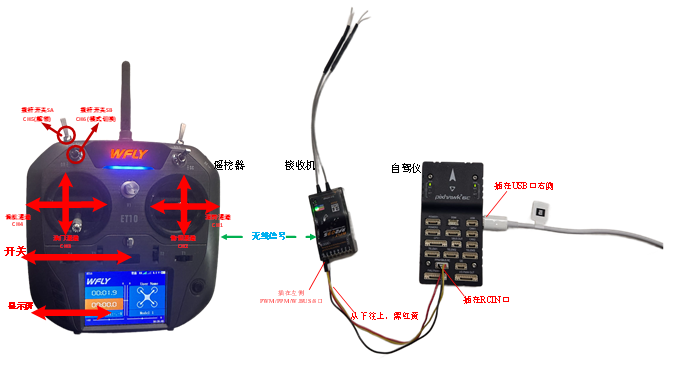
The remote controller recommended for use in this course adopts the “Mode 2” (American hand) control layout, where the left joystick controls throttle and yaw, while the right joystick controls roll and pitch. In the remote controller, roll, pitch, throttle, and yaw correspond to receiver channels CH1 to CH4, respectively; the upper-side toggle switches on the left and right correspond to CH5 and CH6 channels, used to trigger flight mode switching.
The throttle stick (CH3 channel) corresponds to a PWM signal ranging approximately from 1100 to 1900 as the stick moves from the lowest to the highest position (this range may vary slightly depending on the specific receiver or remote controller, thus calibration is required). The roll (CH1 channel) and yaw (CH4 channel) sticks correspond to a PWM signal ranging from 1100 to 1900 as they move from the far left to the far right. The pitch (CH2 channel) stick corresponds to a PWM signal ranging from 1900 to 1100 as it moves from the lowest to the highest position. CH5 and CH6 are three-position switches, with the top position (farthest from the user), middle position, and bottom position (closest to the user) corresponding to PWM values of 1100, 1500, and 1900, respectively.

2. Configuration and Calibration Steps:
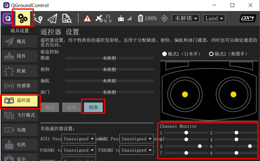
- Connect the Pixhawk to the receiver correctly, and connect the Pixhawk to the computer via a USB data cable. Power on the remote controller and launch the QGroundControl ground station software. Click the “Radio” tab shown in the lower-right image.
-
Move the remote controller’s CH1 to CH5 channels sequentially from left to right (or top to bottom, as shown in the upper-right image), and observe the white dots in the red box area on the right side of the ground station interface. If the white dots for channels 1, 2, 4, 5, and 6 move from left to right (PWM from 1100 to 1900), and the dot for channel 3 moves from right to left, the remote controller configuration is correct. Otherwise, reconfigure the remote controller.
-
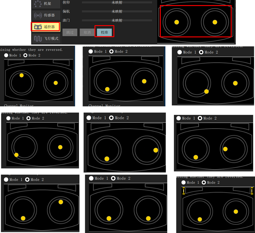
Click the “Calibrate” button shown in the lower-right image, and follow the on-screen prompts to calibrate the remote controller.
- Click the “Calibrate” → “Next” button on the QGC ground station, then move the joysticks to the positions shown in the right-hand image (as prompted in real time on the QGC interface) to complete the remote controller calibration.
Flight Mode Setup
-
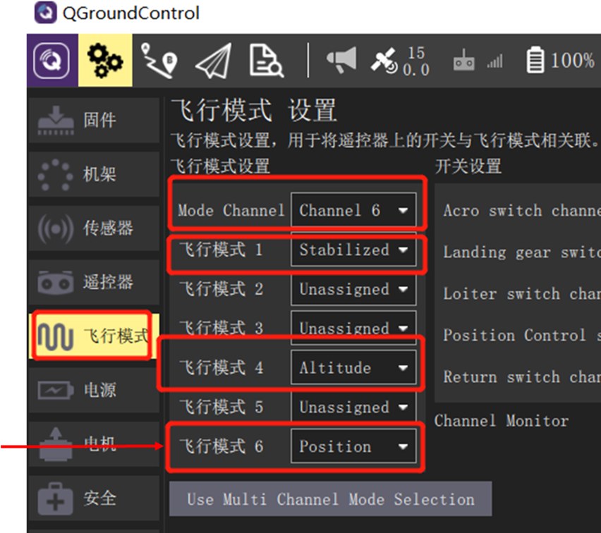
After completing the above remote controller calibration steps, click into the “Flight Modes” setup page in the ground station. Select “Mode Channel” as Channel 6 (the channel previously tested). Since CH6 is a three-position switch, its top, middle, and bottom positions correspond to “Flight Mode 1”, “Flight Mode 4”, and “Flight Mode 6”, respectively.
-
Assign these three flight modes as follows: “Stabilized” (attitude-only control), “Altitude” (attitude and altitude control), and “Position” (attitude, altitude, and horizontal position control). In subsequent hardware-in-the-loop simulations, switching between these modes will allow you to experience different control behaviors.