Serial Module Documentation
Toolbox: ADC and Serial
Introduction
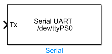
One-sentence Description: This module enables serial port data transmission and reception communication between Simulink models and external devices, supporting flexible communication configuration options.
This module is a hardware communication component in the RflySim toolchain’s ADC and Serial interface library. It supports real-time data exchange with various external hardware devices (e.g., sensors, third-party microcontrollers, peripherals) via serial interfaces during Simulink simulation. It is primarily used in semi-physical simulation, hardware-in-the-loop (HIL) simulation, and real-machine deployment scenarios requiring Simulink model integration with external hardware.
The Serial module supports two operational modes: reading and writing. It allows flexible configuration of parameters such as baud rate, frame format, blocking mechanism, and communication protocol. Additionally, it supports both interpreted execution and code generation modes. During simulation and debugging, interpreted execution enables rapid validation of communication logic; during deployment, compiling into C code yields higher communication real-time performance. This module is commonly used in conjunction with PX4 flight controller hardware and other peripheral expansions, providing stable serial communication support for RflySim’s semi-physical simulation and real-machine validation workflows.
Port Descriptions
Input Ports (Inputs)
| Port Name | Data Type | Dimension | Description |
|---|---|---|---|
DataIn |
uint8 |
N×1 | In Writing mode, inputs data to be sent to the serial port; N is the length of the data to be sent |
This input port exists only in Writing mode. In Reading mode, the module has no input ports.
Output Ports (Outputs)
| Port Name | Data Type | Dimension | Description |
|---|---|---|---|
DataOut |
uint8 |
N×1 | In Reading mode, outputs data received from the serial port; N is the configured number of bytes to read |
ByteCount |
double |
1×1 | In Reading mode, outputs the actual number of bytes received after enabling the Output Number of Bytes Receive option |
These output ports exist only in Reading mode. In Writing mode, the module has no output ports.
Parameter Configuration (Parameters)
The following parameters can be configured in the Mask dialog box opened by double-clicking the module:
| Parameter Name | Type | Default Value | Available Values / Range | Description |
|---|---|---|---|---|
Device Name |
string |
/dev/ttyS0 |
Any valid device path | Specifies the serial port device name to communicate with; on Linux systems, paths typically start with /dev/, while on Windows systems, names typically follow the COMx format |
Read or Write to serial |
enum |
Reading |
Reading, Writing |
Selects the serial port operation mode: Writing sends data from Simulink to the serial port, Reading reads data from the serial port into Simulink |
Baud Rate |
int |
115200 |
Standard serial baud rate enumeration values | Sets the serial communication baud rate; must match the baud rate of the connected external device |
Blocking |
bool |
false |
true, false |
Enables or disables blocking mode: when enabled, the module waits for the send/receive operation to complete before continuing simulation; otherwise, it proceeds directly |
Output Number of Bytes Receive |
bool |
false |
true, false |
Available in Reading mode: when enabled, outputs an additional signal indicating the actual number of bytes received |
Enable Terminator |
bool |
false |
true, false |
Available in Writing mode: when enabled, appends a terminator (line feed character) to the end of each transmitted data packet |
Enable Header |
bool |
false |
true, false |
Available in Writing mode: when enabled, adds a header identifier to the transmitted data packet, suitable for communication protocols requiring packet headers |
Enable Comm Protocol |
bool |
false |
true, false |
When enabled, uses a specified communication protocol to process data transmission, suitable for complex communication scenarios |
indicate number of bytes to read |
int |
4 |
Positive integers ≥ 1 | In Reading mode, specifies the number of bytes to read |
Simulate using |
enum |
Interpreted Execution |
Interpreted Execution, Code Generation |
Selects the simulation execution mode: interpreted execution is suitable for debugging, while code generation mode offers higher performance and supports deployment |
Parameter Setting Notes
Device Name
Serial device naming conventions vary across operating systems: Linux systems typically use paths like /dev/ttyUSB0, /dev/ttyS0, while Windows systems typically use formats like COM1, COM3. Modify this parameter to match the actual connected device.
Read or Write to serial
Selecting different operation modes automatically adjusts the module’s port structure: selecting Writing creates an input port and no output ports; selecting Reading creates output ports and no input ports. Enabling byte count output adds an additional output port.
indicate number of bytes to read
Applies only in Reading mode. The module pre-allocates a buffer and reads the specified number of bytes. If fewer bytes are received than specified, blocking mode waits until the buffer is full, while non-blocking mode outputs the received data and reports the actual number of bytes received via the ByteCount port.
Simulate using
To generate C code for semi-physical simulation or real deployment, select Code Generation mode. For development and debugging, Interpreted Execution mode facilitates troubleshooting.
Module Characteristics (Block Characteristics)
| Characteristic | Value |
|---|---|
| Supported Data Types | double, single, uint8, uint16, uint32, int8, int16, int32 |
| Direct Feedthrough | Yes (Writing mode) / No (Reading mode has no input) |
| Sample Time | Discrete |
| Code Generation Support | Yes |
Data Communication Protocol
This module implements standard serial port (UART) communication, adhering to the standard RS-232 serial communication specification. Data format and communication rules are configurable by the user, with no additional proprietary protocols.
Related Modules
| Module Name | Description |
|---|---|
ADC Read |
Collects analog-to-digital conversion data from external devices, enabling simulation and analog signal interaction with external hardware |
Usage Example
For related usage examples, please refer to the following path:
Please refer to
Readme.pdfin the above path for complete example descriptions and operational steps.
Notes and Common Issues
- Initialization Order: A single serial port cannot be simultaneously opened and occupied by multiple Serial modules or other processes; otherwise, a port-open failure error will be triggered. Ensure that each serial port is used exclusively by one Serial module, and close any other programs on the system that may be using the same port.
- Parameter Matching Requirements: The baud rate configured for the module must exactly match the baud rate of the connected external hardware device; otherwise, garbled characters or communication failures may occur. When enabling options such as termination character, header, or custom communication protocol, the parameter configuration must align precisely with the communication protocol of the peer device; otherwise, correct data parsing cannot be achieved.
- Device Name Format: Serial device naming conventions differ across operating systems. On Linux systems, device names typically follow paths such as
/dev/ttyUSB0or/dev/ttyS0; on Windows systems, they typically appear asCOM1,COM3, etc. Please enter the correct device name according to your actual operating system—incorrect device names will result in port-open failures. - Blocking Mode Impact: If Blocking mode is enabled, the simulation step size will be blocked by serial transmission/reception operations; if the peer device does not return data, the simulation will stall. To ensure real-time simulation execution, please disable Blocking mode.
- Bytes-to-Read Configuration: In Reading mode, the
indicate number of bytes to readparameter must be configured accurately based on the actual length of the communication data packets. If the configured value is smaller than the actual packet length, data truncation will occur; if larger, the system will wait for additional data, causing delays or data misalignment. - Sample Time Matching: The sample time of the Serial module must match the overall simulation step size of the model. If the sampling frequency is set too high—exceeding the actual data transmission rate of the serial port—it may lead to packet loss or buffer overflow. In non-blocking mode, it is recommended to set the sampling interval reasonably based on the baud rate and the amount of data transmitted per transaction.
- Execution Mode Selection: For debugging communication logic, selecting
Interpreted Executionmode is sufficient. For long-duration simulations or code generation and deployment, switch toCode Generationmode; otherwise, simulation speed will be significantly reduced. - Permission Issues (Linux Systems): When using USB-to