i6s
FOS i6S 
1. Product Introduction
The FS-i6S is a groundbreaking product by FOS, inheriting classic design elements while integrating new features. As a 10-channel transmitter, the i6S is suitable for multi-rotor aircraft, FPV drones, excavator models, and other engineering vehicle models. Its capacitive touch screen significantly enhances user experience, and its support for both Chinese and English firmware meets the needs of the vast majority of RC enthusiasts!
2. Transmitter Configuration
1) Overview of the transmitter is shown in the figure below.
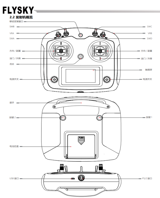
2) Transmitter Antenna: The FS-i6S transmitter features an internal copper-tube omnidirectional dual-antenna system.
3) Sticks / Knobs / Switches / Buttons: The FS-i6S includes 2 sets of sticks, 4 sets of switches, 2 sets of knobs, and 2 sets of buttons.
• Sticks: Used to control ailerons, elevator, throttle, rudder, and auxiliary channels.
• Switches: Used to control auxiliary channels or the timer function.
• Knobs: Used to control auxiliary channels.
• Buttons: Used to control auxiliary channels or the timer function.
4) Status Indicator Light: The status indicator light indicates the power status and operational state of the transmitter.
• Off: Transmitter power is turned off.
• Solid blue: Transmitter power is on and operating normally.
Note: During use, to ensure signal quality, the antenna should be kept perpendicular to the model’s fuselage. When operating, adjust the antenna orientation to avoid pointing the antenna’s tip directly toward the model body. Do not grip the transmitter antenna tightly, as this will significantly weaken the radio signal’s propagation quality and strength, potentially causing loss of control. Do not pull on the receiver’s antenna, nor bundle the antenna together with servo wiring.
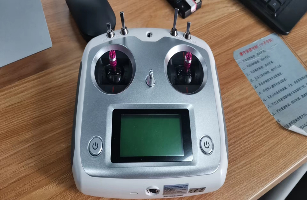
5) Physical photos of the receiver and transmitter are shown in the figure to the right.
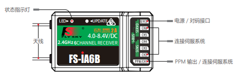
6) Receiver Antenna: The FS-iA6B uses a copper-tube omnidirectional dual-antenna system.
7) Status Indicator Light: The status indicator light indicates the power status and operational state of the receiver.
• Off: Receiver power is not connected.
• Solid red: Receiver power is connected and operating normally.
• Rapid flashing: Receiver is in binding mode.
• Slow flashing: The paired transmitter is not powered on or the signal has been lost.
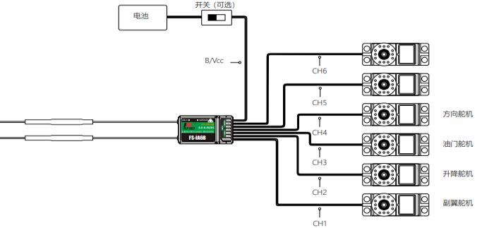
8) Interfaces: Interfaces are used to connect the receiver to various components of the model.
• PPM/CH1: Connects to a servo for CH1 channel or outputs PPM signal.
• CH2 ~ CH6: Interfaces for connecting servos, power, or other components.
• B/VCC: Used to connect the binding wire during binding; during normal operation, used to connect the power line, with an input voltage range of 4.0–8.4V.
• SERVO: Used to connect the i-BUS receiver’s extended channels, outputting i-BUS/S.BUS signals.
• SENS: Used to connect various sensors.
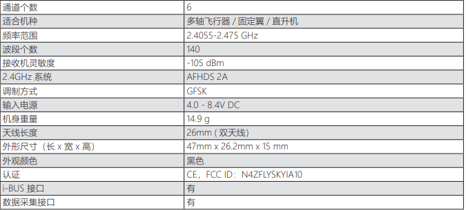
9) Receiver specifications (FS-iA6B) are shown in the figure below.
10) Receiver and Servo Installation: Please follow the instructions below to install the receiver and servos.
Note: The FOS i6S transmitter is primarily intended for simulation use. Its channel configuration method can refer to the preceding Loongtech AT9S Pro.