3DOutput Module Documentation
Toolbox: RflySim Model
Introduction
One-sentence description: Encapsulates and integrates the 3D model style, actuator responses, and six-degree-of-freedom (6-DOF) motion information of UAV platforms into a standardized 60-dimensional 3D information vector for visualization and rendering in RflySim3D.
This module belongs to the RflySim Model interface library and serves as the core data integration module connecting Simulink flight control simulation with the RflySim3D visualization environment. It supports multi-vehicle simulation scenarios, allowing the vehicle ID to be specified via the CopterID parameter. The module receives three types of input signals: (1) up to 16-dimensional actuator signals (motor speeds in RPM) output by the actuator response module, (2) 3D model type information of the vehicle output by the parameter module, and (3) 6-DOF dynamic bus signals output by the 6DOF module. It then consolidates and encapsulates these into a standardized 60-dimensional vehicle information vector, VehileInfo60d.
The encapsulated 3D information vector is transmitted to CopterSim, which forwards it to RflySim3D, enabling real-time 3D visualization of vehicle motion states and actuator actions. This makes it an indispensable visualization output component in the PX4 flight control algorithm simulation and validation workflow.
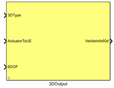
Port Descriptions
Input Ports
| Port Name | Data Type | Dimension | Description |
|---|---|---|---|
3DType |
double |
1×1 |
3D model style of the vehicle, typically specified by the Param_uavType parameter |
ActuatorToUE |
double |
1×16 |
Collection of actuator response signals; motor speeds are in RPM, output by the actuator response module |
6DOF |
double |
1×6 |
6-DOF bus signal, output by the 6DOF module |
Output Ports
| Port Name | Data Type | Dimension | Description |
|---|---|---|---|
VehileInfo60d |
double |
1×60 |
Encapsulated 3D vehicle information vector |
Parameter Configuration
The following parameters can be configured in the Mask dialog box opened by double-clicking the module:
| Parameter Name | Type | Default Value | Available Values/Range | Description |
|---|---|---|---|---|
CopterID |
int |
1 |
1~255 |
Vehicle ID number for which 3D display information is to be output |
Parameter Description
CopterID
This parameter specifies the vehicle ID for which 3D display information is to be output. In multi-vehicle simulation scenarios, each vehicle must be assigned a unique CopterID. For single-vehicle simulation, the default value of 1 is sufficient.
Module Characteristics
| Characteristic | Value |
|---|---|
| Supported Data Types | double, single |
| Direct Feedthrough | Yes |
| Sample Time | Inherited |
| Code Generation Support | No |
Data Communication Protocol
This module does not involve network communication.
Related Modules
| Module Name | Description |
|---|---|
ActuatorModel |
Outputs actuator response signals, usable as input to this module |
6DOF |
Outputs 6-DOF bus signals, usable as input to this module |
Param_uavType |
Provides vehicle 3D model type parameters, usable as input 3DType for this module |
VehicleInfoSender |
Receives the 3D vehicle information output by this module and sends it to the visualization window |
Notes and Common Issues
- Initialization Order: The RflySim 3D visualization environment must first complete initialization and binding of the scene and vehicle IDs. Before simulation starts, ensure that the RflySim3D software has been correctly launched and that the
CopterIDconfigured in this module matches the ID of the vehicle added to the simulation scene. ID conflicts may cause incorrect positioning or failure to load 3D models for multiple vehicles. - Sample Time Matching: The 60-dimensional 3D information vector output by this module must be sent to the RflySim3D visualization service via the
SendToUEmodule. Ensure that the sample time of this module matches that of theSendToUEmodule and the corresponding vehicle flight control model. Excessive differences in sample time steps may cause stalling or frame skipping in the 3D visualization. - Input Signal Dimension Requirements: The
ActuatorToUEinput supports up to 16-dimensional actuator signals. For different vehicle types (e.g., multirotors, fixed-wing, VTOL), ensure the actual dimension of this input does not exceed 16. Exceeding this limit will prevent correct parsing of actuator information for 3D visualization, leading to abnormal animations of control surfaces or rotors. - 6DOF Input Requirements: This module relies on the 6-DOF pose signal output by the
6DOFmodule. Ensure this input is properly connected. An unconnected or incorrectly connected signal will cause abnormal vehicle position or orientation display in the 3D scene, or even prevent the vehicle model from displaying. - Vehicle Model Matching: The
3DTypeinput must match the actual vehicle type being used. Typically, this is connected to the output of theParam_uavTypeparameter. Mismatched types will result in incorrect 3D models being loaded in the visualization scene.
Changelog
v4.0(2024-01-01): Initial release. Provides basic 3D vehicle display information encapsulation functionality, supports configurable vehicle ID input, and outputs a 60-dimensional 3D vehicle information vector.