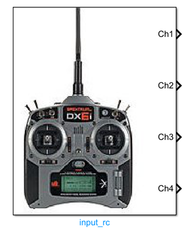
Input_rc Module Documentation
Toolbox: Sensors and Actuators
Introduction
One-sentence Description: Acquires and outputs remote controller input signals from the PX4 side, supporting customizable channel selection and various remote controller status information.
This module belongs to the Sensors and Actuators interface library of the RflySim toolchain and is used to obtain raw remote controller input data received by the PX4 flight controller on the Simulink side. Based on user configuration, the module can output PWM pulse width values for specified channels, and optionally output auxiliary information such as the total detected channel count, remote controller failsafe status, input source type, received signal strength indicator (RSSI), and connection loss status, satisfying diverse drone remote control simulation development requirements.
This module relies on the remote controller input parsing results from the PX4 flight controller. In the simulation chain, PX4 parses real remote controller signals or simulation-generated remote control signals and passes them to this module. Users can directly read and utilize the data in custom control algorithms within Simulink, supporting typical scenarios such as hardware-in-the-loop simulation and remote controller controller development and debugging, without requiring additional development of remote controller signal reception and parsing logic.
Port Descriptions
Input Ports (Inputs)
This module has no input ports.
Output Ports (Outputs)
| Port Name | Data Type | Dimension | Description |
|---|---|---|---|
rc_channels |
uint16 |
N×1 |
N is the number of selected channels; outputs the PWM pulse width values of the corresponding selected remote controller channels |
channel_count |
uint32 |
Scalar | Total number of remote controller channels detected by the PX4 detector; activated only when the "Channel Count" output option is enabled |
rc_failsafe |
boolean |
Scalar | Remote controller failsafe flag; true indicates the remote controller transmitter has triggered a FailSafe signal or is out of operational range; activated only when the "RC Failsafe" output option is enabled |
rc_input_source |
uint8 |
Scalar | Enumerated value indicating the source of the remote controller input signal; definitions are given in RC_INPUT_SOURCE_ENUM.m; activated only when the "RC Input Source" output option is enabled |
rssi |
int |
Scalar | Received Signal Strength Indicator; range: <0 undefined, 0 no signal, 255 full signal reception; activated only when the "RSSI" output option is enabled |
rc_lost |
boolean |
Scalar | Remote controller connection status flag; true indicates that no valid data frame was received within the expected time, meaning the connection has been lost; activated only when the "RC Lost Connection" output option is enabled |
Parameter Configuration (Parameters)
The following parameters can be configured in the Mask dialog box opened by double-clicking the module:
| Parameter Name | Type | Default Value | Optional Values/Range | Description |
|---|---|---|---|---|
SelectedChannels |
vector of uint16 |
[1,2,3,4] |
Each element ranges from 1 to the maximum supported channel count | Remote controller channel numbers to be output |
OutputChannelCount |
boolean |
false |
true/false |
Whether to output channel count information |
OutputRcFailsafe |
boolean |
false |
true/false |
Whether to output the remote controller failsafe flag |
OutputRcInputSource |
boolean |
false |
true/false |
Whether to output the remote controller input source information |
OutputRssi |
boolean |
false |
true/false |
Whether to output the received signal strength indicator |
OutputRcLost |
boolean |
false |
true/false |
Whether to output the remote controller connection loss flag |
SampleTime |
double |
0.01 |
>0 |
Module sampling time, in seconds |
Parameter Setting Descriptions
SelectedChannels
This parameter specifies the remote controller channel numbers to be output. For example, entering [1,2,3,4] indicates outputting the PWM signal values for channels 1–4; the dimension of the output port rc_channels is determined by the number of channels specified by this parameter.
Optional Output Control Parameters
The five parameters OutputChannelCount, OutputRcFailsafe, OutputRcInputSource, OutputRssi, and OutputRcLost control whether the corresponding information is output. When a parameter is enabled, the module adds the corresponding output port to output the specified information.
SampleTime
This parameter specifies the sampling interval for the module to read remote controller data from the simulated flight controller, in seconds. A value of 0.01 generally suffices for most simulation scenarios.
Module Characteristics (Block Characteristics)
| Characteristic | Value |
|---|---|
| Supported Data Types | double, single, uint16, uint32, boolean |
| Direct Feedthrough | No |
| Sample Time | Discrete |
| Code Generation Support | No |
Data Communication Protocol
This module does not involve network communication.
Related Modules
| Module Name | Description |
|---|---|
Output_pwm |
Outputs PWM signals to drone actuators |
IMU_sim |
Simulates inertial measurement unit data output |
GPS_sim |
Simulates GPS position and velocity data output |
Baro_sim |
Simulates barometric altimeter data output |
Mag_sim |
Simulates magnetometer data output |
Usage Example
For related usage examples, refer to the following path:
Please refer to
Readme.pdfin the path above for complete example descriptions and operational steps.
Notes and Common Issues
- Initialization Sequence: This module relies on the PX4 low-level communication link initialization in the RflySim simulation environment. It must be placed within an enabled subsystem in the Simulink model, and the remote controller signal should only be read after the flight controller completes its initialization. Otherwise, it may output invalid zero-value data.
- Sample Time Matching: The module’s sample time is recommended to match the flight controller’s state update cycle (typically 0.004 s to 0.01 s). An overly large sample time will cause remote controller command update delays, while an overly small sample time introduces unnecessary performance overhead.
- Failsafe State Judgment: The reliability of the RC Failsafe output depends on the hardware configuration of the remote controller receiver. Some low-cost PPM receivers do not actively report failsafe states; therefore, it is recommended to jointly assess the remote controller link status by combining the RC Lost Connection output, avoiding misjudgment based on a single signal.
- Channel Selection Configuration: The selected channel index must not exceed the maximum number of channels actually detected by PX4. If the configured channel index exceeds the detection range, the corresponding output will remain at the initial zero value. You can enable the Channel Count output to verify the actual number of detected channels.
- RSSI Signal Range Explanation: The RSSI output valid range is 0–255. A value less than 0 indicates that the current remote controller input source does not support RSSI output, which is not a module fault. To use the RSSI function, please confirm that your remote controller input source supports this signal output.
- Consistency Between Simulation and Real Hardware: In HITL simulation, this module reads the remote controller signals connected to the real hardware. If using pure simulation (SITL) mode, you must manually input remote controller channel values via Simulink; otherwise, no valid input will be available by default.
Changelog
v4.0(2024-08-12): Initial release, supporting outputs of remote controller channel values, channel count, failsafe status, input source, RSSI, and connection status.