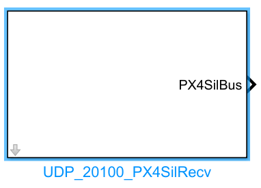
UDP_20100_PX4SilRecv Module Documentation
Toolbox: RflySim Model
Introduction
One-sentence Description: Listens on specified UDP ports in the
20101++2series, receives and parses flight controller state data output by PX4 software-in-the-loop (SITL) simulation.
This module belongs to the RflySim Model interface library and is designed for state data exchange between Simulink algorithms and the PX4 flight controller in PX4 SITL simulation scenarios. It is primarily used in conjunction with the PX4 SITL simulation workflow and external custom control algorithm development. Based on the configured CopterID, the module automatically maps to the corresponding UDP port starting from 20101, receives complete flight controller state data computed by PX4 and sent by CopterSim—including raw GPS information, position, velocity, attitude, etc.—and outputs them as a structured data format for use by custom control algorithms within Simulink.
This module is commonly used in external controller development and validation scenarios based on the RflySim toolchain. Developers can leverage this module to obtain full-state information output by the PX4 flight controller, combine it with custom control logic to generate control commands, thereby enabling simulation validation of extended control algorithms. It supports receiving state data for specific drones in multi-vehicle simulation scenarios.
Port Descriptions
Input Ports (Inputs)
This module has no input ports.
Output Ports (Outputs)
| Port Name | Data Type | Dimension | Description |
|---|---|---|---|
time_boot_ms |
double |
1×1 |
Timestamp of the message, in milliseconds |
copterID |
double |
1×1 |
Drone ID, numbered starting from 1 |
GpsPos |
double |
1×3 |
Estimated GPS position, format: [latitude, longitude, altitude]; latitude and longitude in degrees, altitude in meters |
GpsVel |
double |
1×3 |
Estimated GPS velocity, in NED coordinate system, units: m/s |
gpsHome |
double |
1×3 |
Home point GPS position, format: [latitude, longitude, altitude]; latitude and longitude in degrees, altitude in meters |
relative_alt |
double |
1×1 |
Relative altitude, in meters |
hdg |
double |
1×1 |
Heading angle, in NED coordinate system, units: degrees, range: 0~360 |
satellites_visible |
double |
1×1 |
Number of visible satellites |
fix_type |
double |
1×1 |
GPS fix type; 3 indicates 3D fix (high accuracy) |
AngEular |
double |
1×3 |
Estimated attitude Euler angles [roll, pitch, yaw], in radians |
localPos |
double |
1×3 |
Estimated local position, in NED coordinate system, units: meters |
localVel |
double |
1×3 |
Estimated local velocity, in NED coordinate system, units: m/s |
pos_horiz_accuracy |
double |
1×1 |
GPS horizontal positioning accuracy, in meters |
pos_vert_accuracy |
double |
1×1 |
GPS vertical positioning accuracy, in meters |
Note: Reserved fields in the original output structure are not exposed by default; they can be accessed via custom configuration if needed [to be confirmed].
Parameter Configuration (Parameters)
The following parameters can be configured in the Mask dialog box opened by double-clicking the module:
| Parameter Name | Type | Default Value | Optional Values/Range | Description |
|---|---|---|---|---|
CopterID |
int |
1 |
1~255 |
Drone ID, used to identify the specific drone whose data is to be listened to |
GPS Orin latLon (degree) |
double vector |
[31.0, 121.0] |
Any valid latitude/longitude | Latitude and longitude of the GPS origin in the simulation environment, format: [latitude, longitude], units: degrees |
GPS Orin Altitude (m) |
double |
10.0 |
Any valid altitude | Altitude of the GPS origin in the simulation environment, units: meters |
Sample Time (s) |
double |
0.01 |
>0 |
Module sampling time in Simulink simulation, units: seconds |
Parameter Setting Descriptions
CopterID
This module is a single-drone listening module. CopterID determines the UDP port corresponding to the drone to be monitored. The port number is calculated as 20100 + 2 * CopterID; for example, for ID 1, the listening port is 20102.
GPS Orin latLon (degree)
This parameter defines the latitude and longitude of the GPS origin in the simulation environment, used to convert the ENU local coordinate system to the WGS84 global latitude/longitude coordinate system. It must match the simulation environment configuration.
GPS Orin Altitude (m)
This parameter defines the altitude (elevation) of the GPS origin in the simulation environment, used for altitude conversion calculations. It must match the simulation environment configuration.
Sample Time (s)
This parameter specifies the sampling period of the module in Simulink simulation, in seconds. Since the PX4 flight controller typically updates state data at 100 Hz, a value of 0.01 s is recommended.
Module Characteristics (Block Characteristics)
| Characteristic | Value |
|---|---|
| Supported Data Types | double, single, uint32_t, int32_t, float |
| Direct Feedthrough | No |
| Sample Time | Discrete |
| Code Generation Support | Yes |
Data Communication Protocol
This module communicates via UDP, listening on ports following the rule: port number = 20100 + CopterID + 1, i.e., ports in the 20101++2 series. Data is encapsulated using a custom structure format:
-
Overall received data encapsulation format:
-
Load data format
outHILStateData:struct outHILStateData{ uint32_t time_boot_ms; // Message timestamp, unit: ms uint32_t copterID; // Aircraft ID, numbered starting from 1 int32_t GpsPos[3]; // GPS estimated position: latitude/longitude in degrees * 1e7, altitude in meters * 1e3 (positive upward) int32_t GpsVel[3]; // GPS estimated velocity, NED frame, unit: m/s * 1e2 (i.e., cm/s) int32_t gpsHome[3]; // Home position GPS coordinates, same units as GpsPos int32_t relative_alt; // Relative altitude, same unit as GpsPos altitude int32_t hdg; // Heading angle, NED frame, unit: deg * 1000, range 0–360 int32_t satellites_visible; // Number of visible satellites int32_t fix_type; // GPS fix type; 3 indicates 3D fix (high accuracy) int32_t resrveInit; // Reserved integer field float AngEular[3]; // Estimated Euler angles, unit: rad float localPos[3]; // Estimated local position, NED frame, unit: m float localVel[3]; // Estimated local velocity, NED frame, unit: m/s float pos_horiz_accuracy; // GPS horizontal positioning accuracy, unit: m float pos_vert_accuracy; // GPS vertical positioning accuracy, unit: m float resrveFloat; // Reserved floating-point field }
Related Modules
| Module Name | Description |
|---|---|
UDP_20100_PX4ControlSend |
Sends external control commands to the PX4 SITL flight controller via UDP ports in the 20100++2 series |
UDP_RflySim_Send |
Sends aircraft state data to the RflySim visualization interface |
UDP_RflySim_Recv |
Receives user interactive control commands from the RflySim visualization interface |
Usage Example
For relevant usage examples, please refer to the following