RealCtrl28D Module Documentation
Toolbox: RflySim Swarm
Introduction
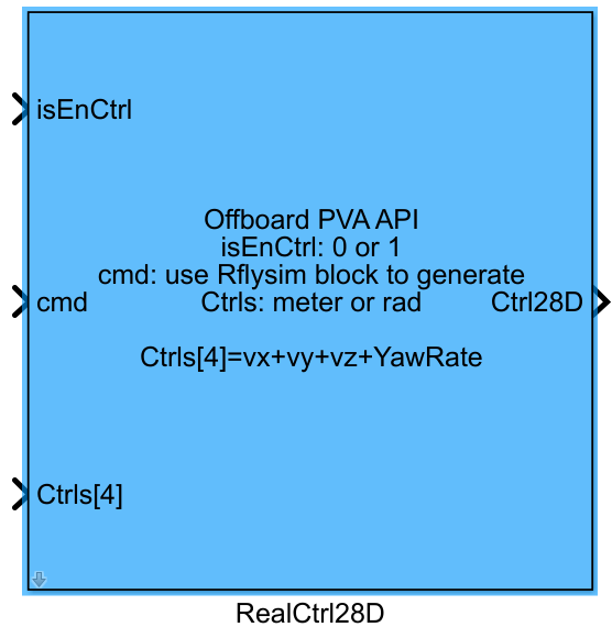
One-sentence description: This module packages multi-dimensional control inputs for UAVs into a standardized 28-dimensional control vector, providing standardized offboard control outputs for the RflySim swarm control toolchain.
The RealCtrl28D module is a control command standardization module within the RflySim Swarm interface library, designed for offboard control of multi-UAV swarms. It supports configuration of position, velocity, acceleration, yaw angle, and yaw angular velocity for UAVs in the NED local coordinate system. Users can freely select the control type for each degree of freedom based on their control algorithm requirements. Additionally, it supports extended modes such as simulating direct RC control and acceleration-to-force conversion. Based on user configuration, this module parses the input control quantities, combines them with control enable signals and mode commands, and outputs a 28-dimensional double-type control vector compliant with the communication protocol. The control commands are ultimately sent to the PX4 flight controller via communication modules such as RflyUdpMavlink, supporting both simulation environments and real-world swarm control development.
This module is primarily intended for advanced swarm control development scenarios within the RflySim toolchain. When used in conjunction with mode command signals generated by mode control modules, it enables various offboard control modes—including position control, velocity control, and acceleration control—making it suitable for both single-vehicle complex mission development and multi-vehicle swarm cooperative mission development. It serves as the core interface module connecting upper-layer custom control algorithms with the lower-layer PX4 flight controller communication layer.
Port Descriptions
Input Ports (Inputs)
| Port Name | Data Type | Dimension | Description |
|---|---|---|---|
isEnCtrl |
double/boolean |
1×1 |
Control enable signal. When true, the module outputs valid control data; when false, all output signals are zeroed. |
cmd |
double |
1×n [to be confirmed] |
Control command, typically generated by the Mode Control module, used for offboard control configuration. |
Ctrls |
double |
1×4 |
Four-dimensional control input; its parsing method is determined by module parameter configuration. |
Output Ports (Outputs)
| Port Name | Data Type | Dimension | Description |
|---|---|---|---|
PackedCtrl |
double |
1×28 |
Packed 28-dimensional control data, output to communication modules (e.g., RflyUdpMavlink) for transmission. |
Parameter Configuration (Parameters)
The following parameters can be configured in the Mask dialog box opened by double-clicking the module:
| Parameter Name | Type | Default Value | Available Values/Range | Description |
|---|---|---|---|---|
Select channels to control |
boolean group |
No default value (user must select) | Options: x, y, z, vx, vy, vz, ax, ay, az, yaw, yawspeed |
Select the channels to be controlled; one control quantity must be selected for each degree of freedom. |
Simulate Rcc Direct |
boolean |
false |
true/false |
Whether to enable simulation of direct RC controller (RCC) control. |
Enable Force |
boolean |
false |
true/false |
Whether to treat acceleration channel inputs as control forces instead of accelerations. |
Sample Time (s) |
double |
0.01 [to be confirmed] |
>0 |
Module execution sample time, in seconds. |
Parameter Setting Instructions
Select channels to control
This parameter selects the control quantities for each degree of freedom: For the X-axis degree of freedom, one of x (position, unit: m), vx (velocity, unit: m/s), or ax (acceleration, unit: m/s²) must be selected; similarly, one must be selected for the Y-axis and Z-axis degrees of freedom. For the yaw degree of freedom, one of yaw (desired yaw angle, unit: rad, range: -π to +π) or yawspeed (yaw angular velocity, unit: rad/s, about the NED coordinate system Z-axis) must be selected. This constraint is necessary to ensure stable UAV control.
Simulate Rcc Direct
When this option is selected, the module directly maps the four-dimensional control input [vx, vy, vz, yawspeed] to RC channel signals [ch1, ch2, ch3, ch4], with input range required to be [-1, 1]. The module automatically maps this to the PWM signal range [1000, 2000], allowing the four-dimensional control input to be used directly as a simulated RC signal.
Enable Force
When this option is selected, the inputs to the selected ax, ay, az channels are parsed as control forces (instead of accelerations), for use in direct force control scenarios.
Sample Time (s)
Specifies the execution sample time of the module in seconds. A suitable value should be set according to control cycle requirements.
Module Characteristics (Block Characteristics)
| Characteristic | Value |
|---|---|
| Supported Data Types | double |
| Direct Feedthrough | Yes |
| Sample Time | Discrete |
| Code Generation Support | No |
Data Communication Protocol
This module outputs a 28-dimensional double control vector for subsequent communication modules (e.g., RflyUdpMavlink) to package and transmit. The module itself does not perform network communication directly.
Related Modules
| Module Name | Description |
|---|---|
HighLevelMode |
Generates the control commands and enable control signals required by this module. |
RflyUdpMavlink |
Receives the 28-dimensional control data output by this module and transmits it to UAV simulation or real UAVs via the MAVLink protocol. |
OffboardPVA |
Further processes the control commands output by this module to adapt to the MAVLink PositionTarget protocol format. |
RflySwarmWaypoint |
Can be used in conjunction with this module to achieve multi-UAV waypoint mission control. |
Notes and Common Issues
- Initialization Order: The
cmdcontrol command must be generated by the [Mode Control] module and cannot be directly customized; otherwise, the control flags required by the MAVLink protocol cannot be correctly generated, leading to failure of offboard control. - Control Channel Constraints: For the three translational degrees of freedom (X, Y, Z), exactly one control channel must be selected from
x,vx, oraxfor each degree of freedom; for the yaw channel, exactly one control channel must be selected fromyaworyawspeed. Failure to meet this constraint will result in unstable or loss of drone control. - Multi-Drone Position Control Enablement: In swarm scenarios using position control, the
isEnCtrlsignal generated by the mode control module cannot be used directly. Custom enable logic is required: control must be enabled only after the drone is armed, and the drone’s current position must be used as the initial control command input to prevent unintended motion upon entering offboard mode due to an initial zero-position command. - Sample Time Matching: The
Sample Time (s)setting of the module must match the sampling frequency of downstream communication modules (e.g.,RflyUdpMavlink) and the entire offboard control loop. Mismatch will cause control command transmission delays or packet loss, affecting flight stability. - Simulate Rcc Direct Mode Description: After enabling this mode, the four-dimensional control input is directly interpreted as simulated RC channel signals, with input values required to remain within
[-1, 1]. The module automatically maps these inputs to a PWM output range of 1000–2000 µs; inputs outside this range will cause abnormal RC signals. - Force Control Mode Description: After enabling
Enable Force, theax,ay, andazinputs are interpreted as forces rather than accelerations; input units must be adjusted accordingly to prevent drone loss of control due to excessive control effort.
Changelog
v4.1.0(2024-12-09): Initial release. Implements packaging of control commands and control quantities into a 28-dimensional communicable format, supporting multi-degree-of-freedom control (position/velocity/acceleration/yaw angle/yaw angular velocity). Adds options for simulated RCC direct control and force control, and supports customizable sample time.