RflySim3D Virtual Lab User Manual (Full Version Only)
1 Overview
1.1 Document Purpose
This document is intended to guide users through drone cognitive learning, virtual assembly, and flight controller wiring debugging operations in the RflySim3D Virtual Lab. Through this manual, users can understand the entry point of the virtual lab, interface navigation methods, model selection process, general interaction methods, as well as standard operating procedures and exception handling methods for each functional module.
1.2 Virtual Lab Entry
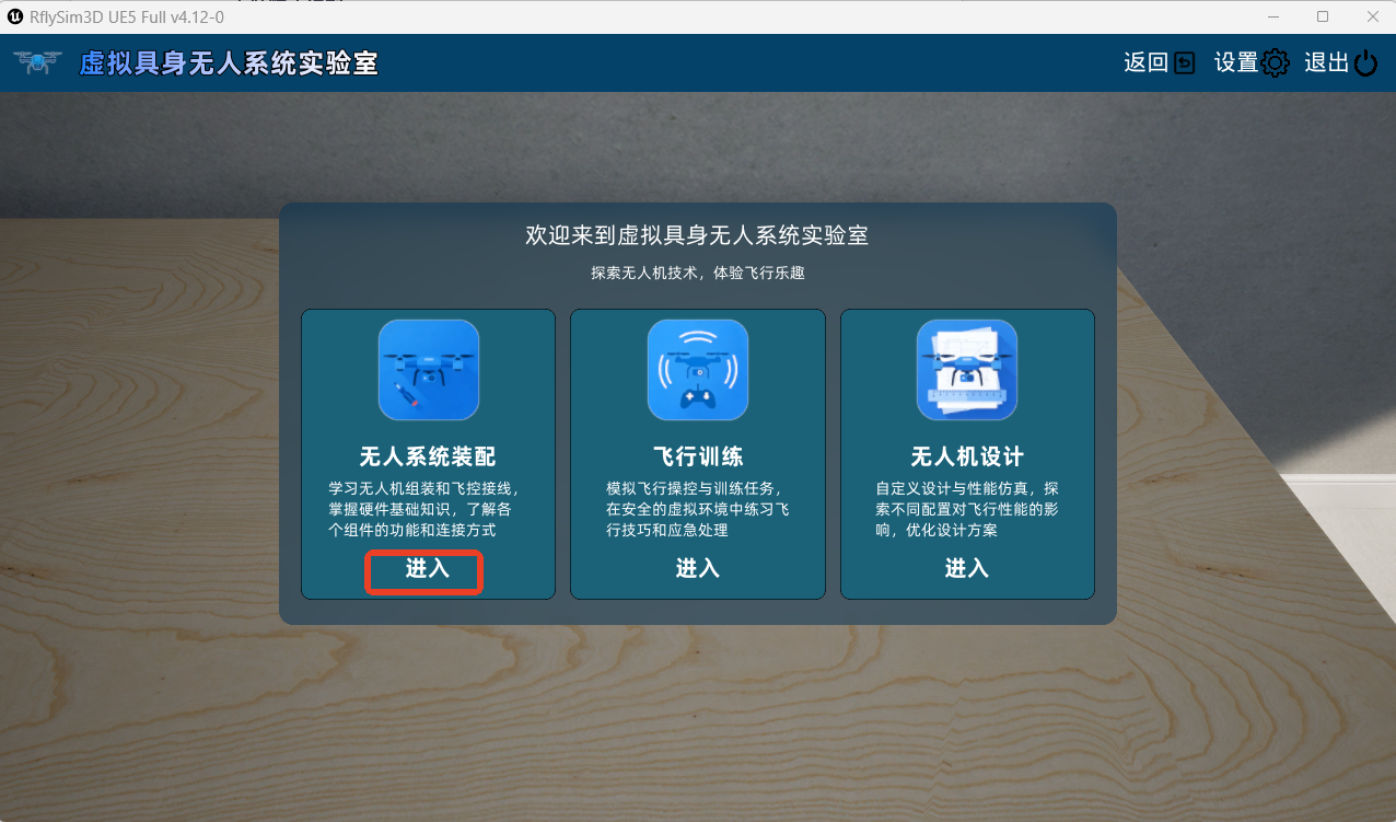
After launching RflySimUE5, click the "Virtual Lab" button in the upper right corner of the window to enter the Virtual Lab homepage.

1.3 Functional Scope
The RflySim3D Virtual Lab is a drone virtual simulation teaching platform based on Unreal Engine. Through 3D visualization and interactive operations, it provides users with a learning experience in drone structure cognition, hands-on assembly, and flight controller wiring.
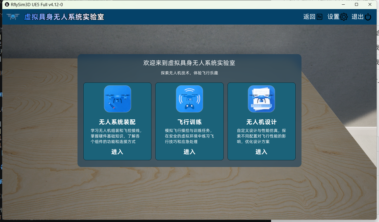
The Virtual Lab currently includes the following functional modules:
| Module Name | Current Status | Function Description |
|---|---|---|
| Unmanned System Assembly | Developed | Includes three sub-modules: Drone Introduction, Drone Assembly, Flight Controller Wiring |
| Flight Training | In Development | Plans to provide drone flight simulation training functions |
| Drone Design | In Development | Plans to provide custom drone design functions |
1.4 Supported Models
The currently supported drone models are as follows:
| Drone Model | Diagram | Number of Rotors | Learning Characteristics |
| --- | --- | --- | --- |
| Quadcopter F450 | 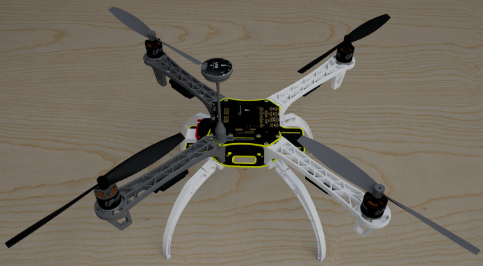 | 4 | Clear structure, suitable for beginners to learn basic drone configuration and motor direction rules |
| Hexacopter |
| 4 | Clear structure, suitable for beginners to learn basic drone configuration and motor direction rules |
| Hexacopter | 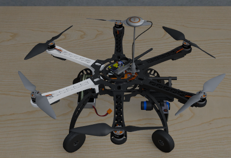 | 6 | More rotors, suitable for further understanding multi-rotor layout and sequential assembly |
| DJI S1000 |
| 6 | More rotors, suitable for further understanding multi-rotor layout and sequential assembly |
| DJI S1000 | 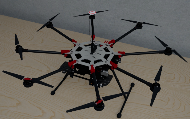 | 8 | Professional-grade octocopter, motor numbers and rotation directions are fixed, suitable for learning identification rules for complex models |
2 Interface Navigation
2.1 Entering the Virtual Lab
On the main interface of the RflySim3D platform, click the "Virtual Lab" entry button to enter the Virtual Lab homepage.
The Virtual Lab homepage contains three entry points:
- "Unmanned System Assembly": Enter the currently available drone structure cognition, assembly, and wiring training.
- "Flight Training": In development, clicking displays a prompt.
- "Drone Design": In development, clicking displays a prompt.
2.2 Entering Unmanned System Assembly
On the Virtual Lab homepage, click the "Unmanned System Assembly" module to enter the assembly selection page.
The assembly selection page contains the following:
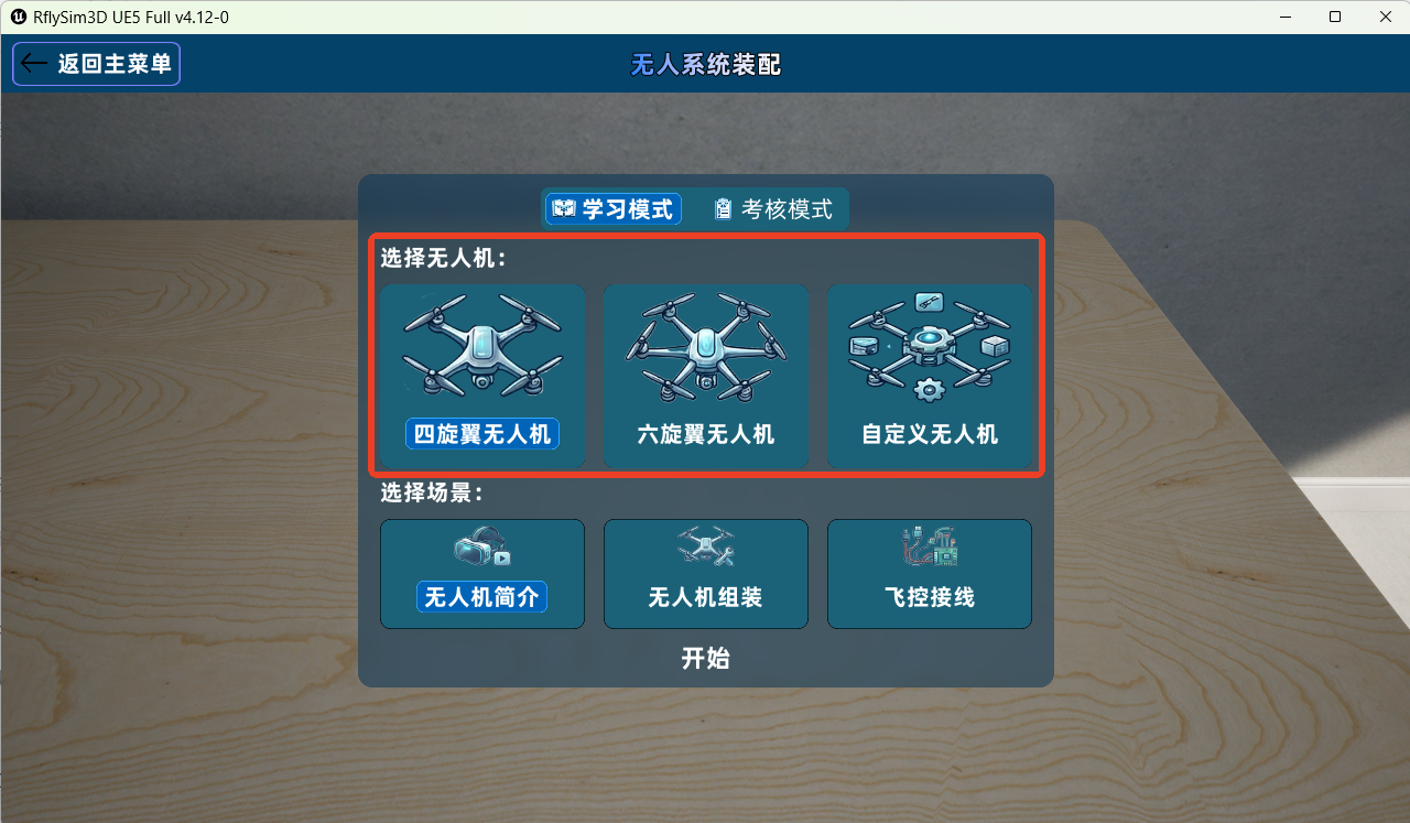
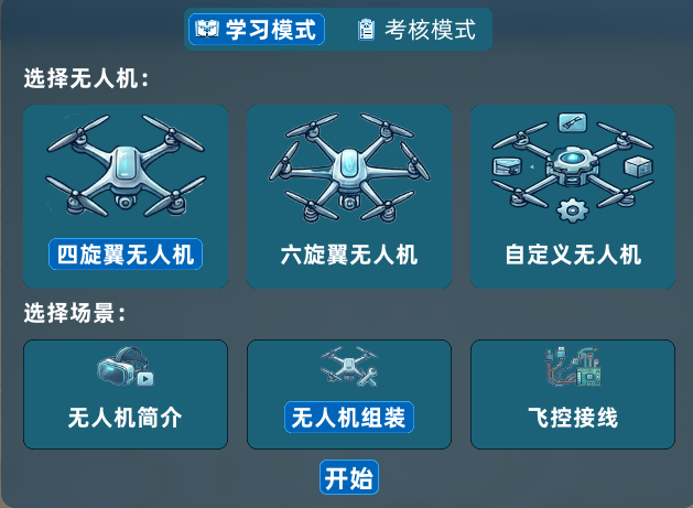
- Drone Selection List: Used to select F450, Hexacopter, or other custom unmanned vehicles (currently includes one DJI S1000 octocopter).
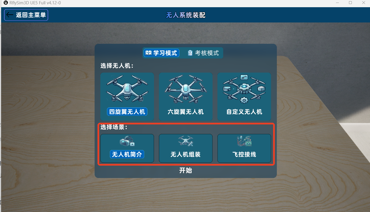
 - Scene Entry: Used to enter "Drone Introduction", "Drone Assembly", "Flight Controller Wiring".
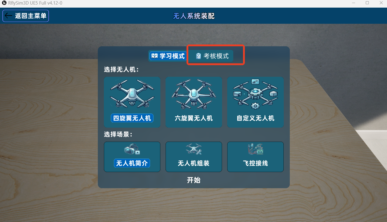
 - Exam Entry: Currently in development, temporarily unavailable.
2.3 Returning and Exiting
The system supports step-by-step return navigation, with each page providing a "Return" button:
| Current Page | Target Page After Clicking "Return" | Diagram |
| --- | --- | --- |
| Drone Introduction, Drone Assembly, Flight Controller Wiring | Return to Assembly Selection Page |  |
| Assembly Selection Page | Return to Virtual Lab Homepage |
|
| Assembly Selection Page | Return to Virtual Lab Homepage |  |
| Virtual Lab Homepage | Return to RflySim3D Platform Main Interface |
|
| Virtual Lab Homepage | Return to RflySim3D Platform Main Interface |  |
|
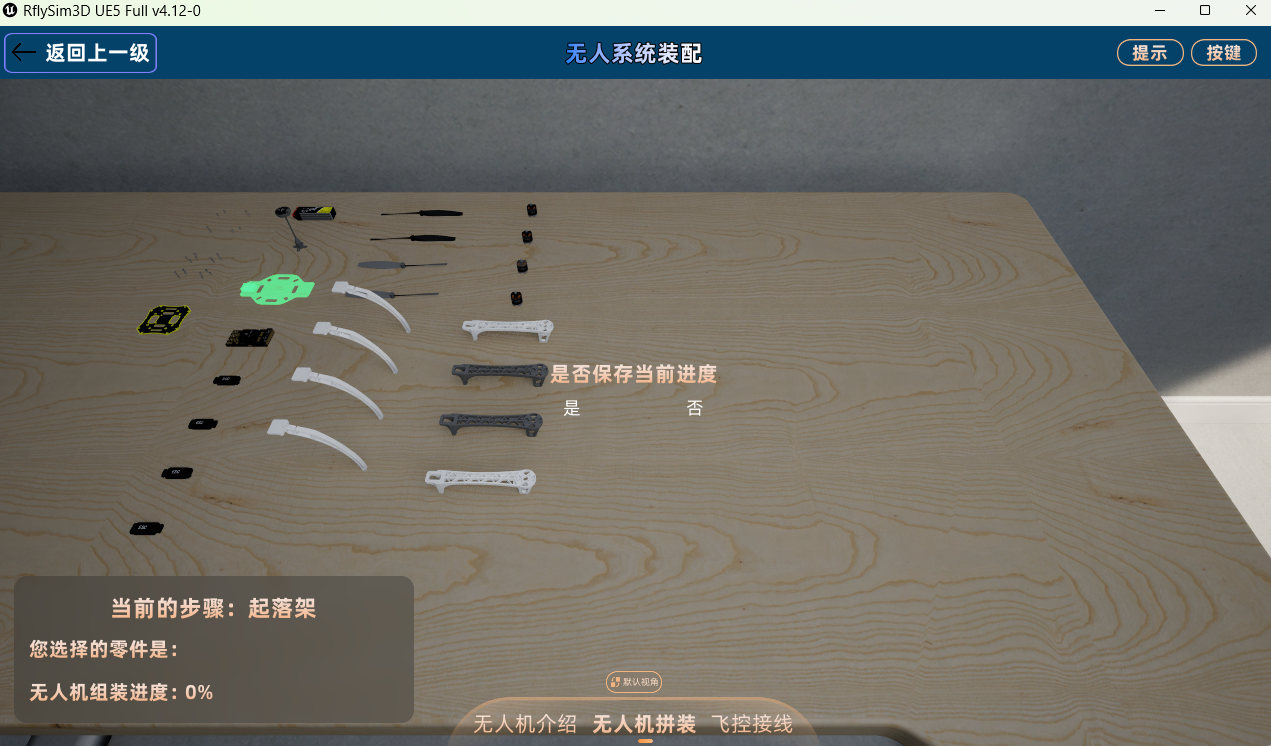
Note: If an assembly or wiring operation is in progress, the system will prompt you to choose whether to save the current progress before switching modules or returning.
3 Drone and Scene Selection
3.1 Selecting a Drone and Scene Module
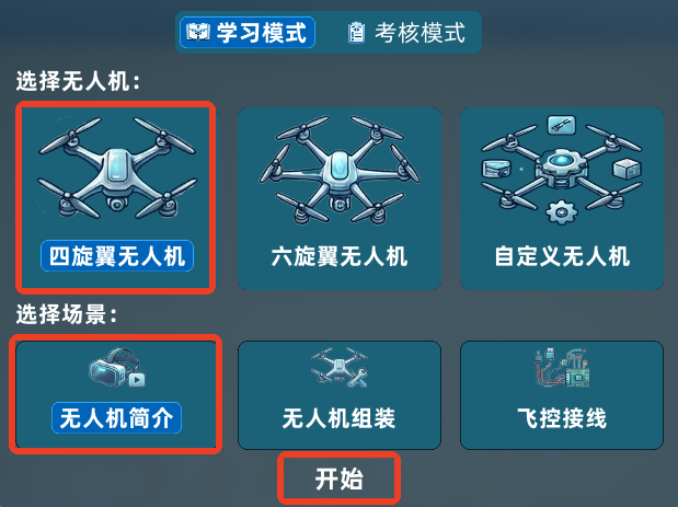
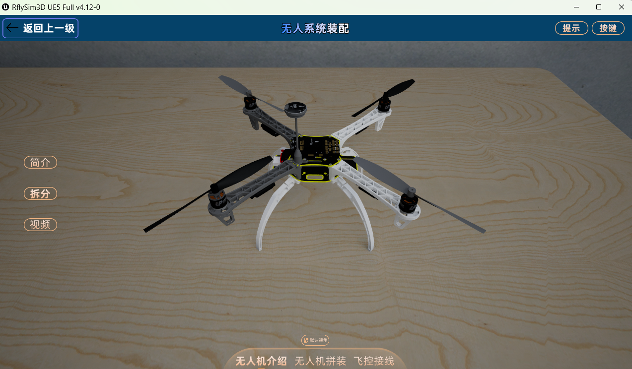
On the assembly selection page, select the model to learn from the drone list. Different models have different numbers of assembly parts, motor numbers, and rotation direction rules. Here, we take the quadcopter as an example. After selecting the drone, you can choose any of the following three scene modules (you can switch to different modules after entering): | Scene Module | Function Description | Recommended Usage Time | | --- | --- | --- | | Drone Introduction | View drone introduction, split/merge structure, view part details, watch instructional videos | Before assembly | | Drone Assembly | Follow system prompts to gradually install parts onto the drone | After structure cognition | | Flight Controller Wiring | Complete wiring between motors, ESCs, and the flight controller, and verify wiring direction | After assembly is complete |
4 General Interaction Operations
4.1 Camera Operations
The following camera operations are common across all scene modules:
| Operation | Mouse/Keyboard | Effect |
|---|---|---|
| Rotate View | Hold left mouse button and drag | View rotates around the model, allowing full observation |
| Zoom View | Scroll the middle mouse wheel | Scroll forward to zoom in, scroll backward to zoom out |
| Pan View | Hold right mouse button and drag | Pan the observation position |
| Restore Default View | Click the "Restore Default View" button on the interface | View returns to the initial position when entering the scene |
Note: If you lose your bearings during observation, you can click the "Default View" button at any time.

4.2 Object Selection and Deselection
| Scene | Selection Method | Deselection Method |
|---|---|---|
| Drone Introduction | Click a part in the exploded state | Click the part again, or click on an empty area |
| Drone Assembly | Click the part highlighted for the current step | If installation is unsuccessful after releasing the mouse, the part automatically returns to its original position |
| Flight Controller Wiring | Click the starting terminal | Click the selected terminal again, or double-click an empty area |
4.3 Color Prompt Rules
| Prompt Color/Effect | Meaning | Diagram |
|---|---|---|
| Green Highlight | Operable object for the current step or correct installation position | 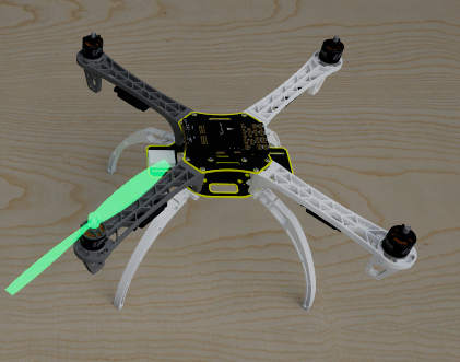 |
| Red Highlight | Current object cannot be installed, connected, or operation is incorrect | 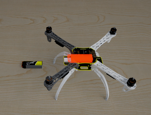 |
| Flashing Highlight | Target terminal that the currently selected object can connect to | 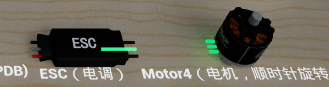 |
| Rotation Effect | Motor or propeller direction has been recognized and displayed by the system | 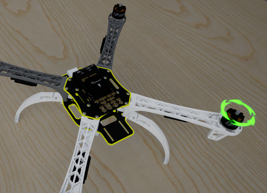 |
5 Drone Introduction Module
The Drone Introduction module helps users establish a preliminary understanding of the overall structure, part functions, and installation positions.
5.1 Viewing Drone Introduction
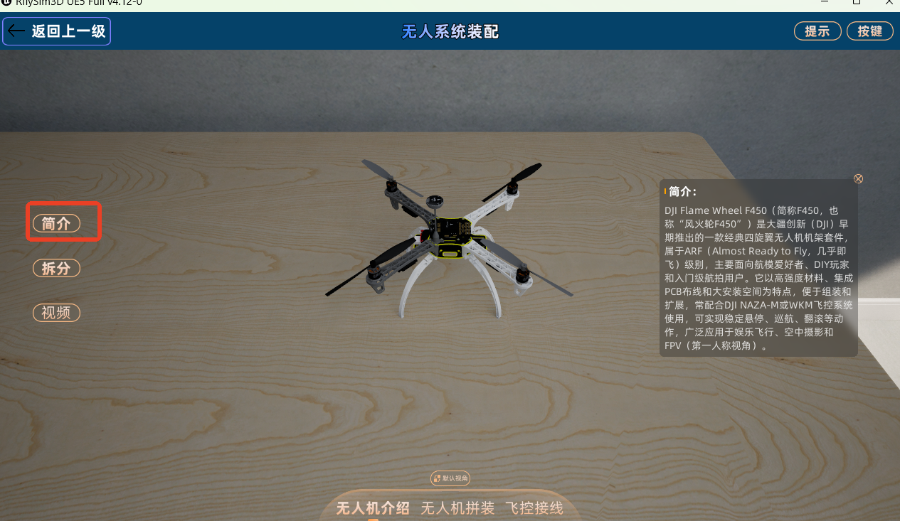
After entering the "Drone Introduction" scene, click the "Introduction" button, and the system will display a text description of the current drone. The introduction usually includes model characteristics, number of rotors, structural composition, and applicable teaching scenarios.
It is recommended to read the introduction first when learning a new model, then proceed with disassembly observation and assembly operations.
5.2 Splitting and Merging
The split/merge function is used to visually display the spatial relationship between the complete drone and its parts.
Split Operation:
- Click the "Split" button.
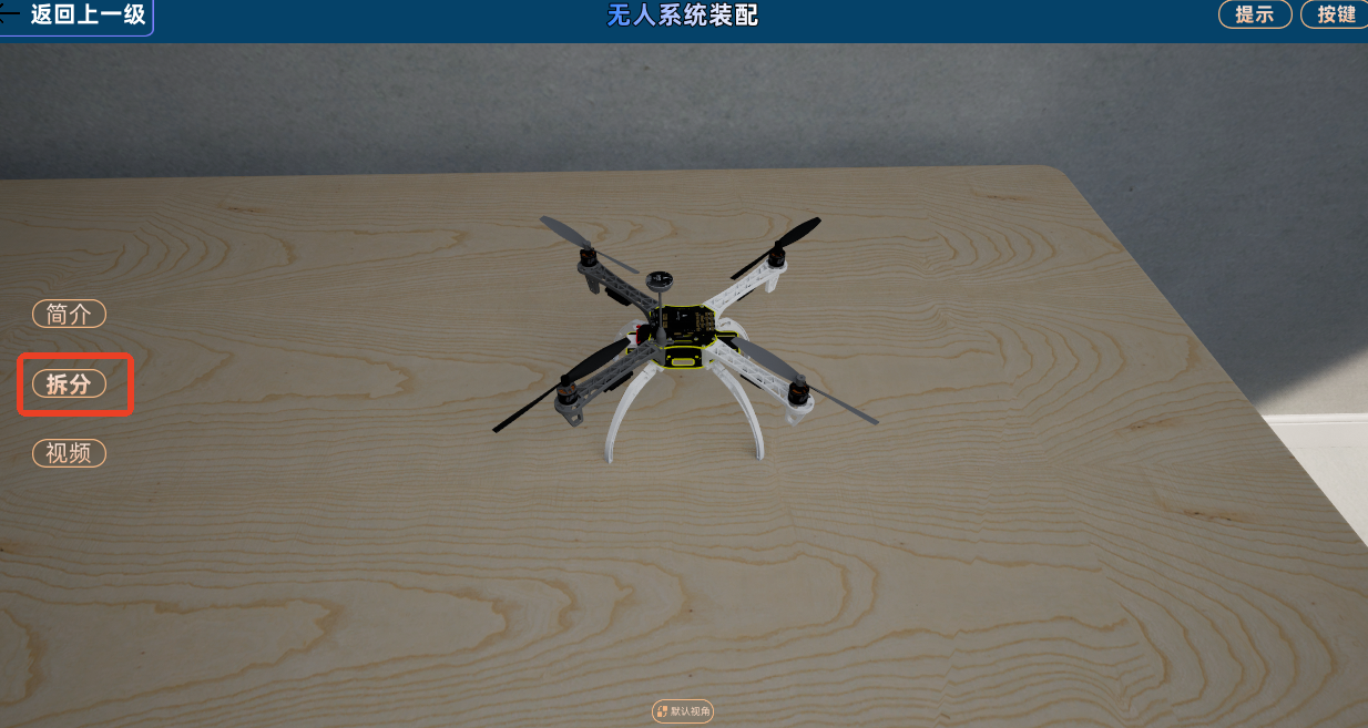
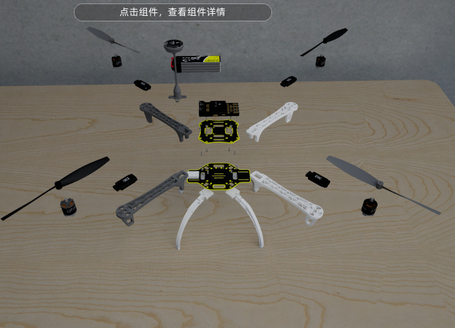
- The drone parts are displayed in an exploded view.
- Click any part (frame, motor, propeller, flight controller, ESC, etc.) to view its introduction.
Merge Operation:
- Click the "Merge" button.
- All parts return to their original assembly positions.
- The drone returns to its complete state.
5.3 Viewing Part Details
In the exploded state, you can view a specific part individually:
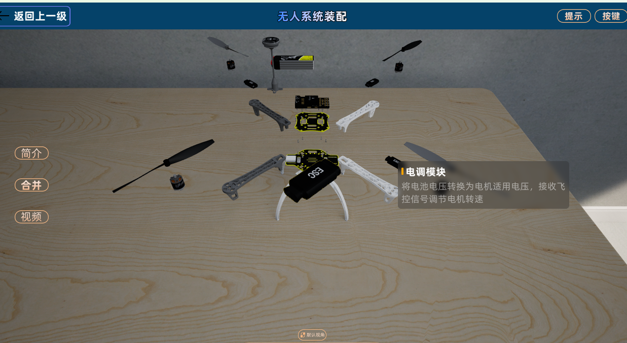
- Left-click on a part.
- The part moves to the center of the view and is displayed enlarged.
- The system displays a text introduction for that part.
- Hold the middle mouse button and drag to rotate and view the part 360 degrees.
To exit the part detail view, click the selected part again, or click on an empty area of the desktop. The part will return to its original position in the exploded view, and the introduction window will close.
5.4 Watching Operation Videos
Click the "Video" button, and the system will pop up a video playback window for watching demonstrations of drone assembly and flight controller wiring operations.
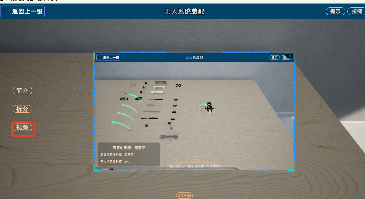
The video player supports the following operations:
| Operation | Method |
|---|---|
| Play/Pause | Click the play or pause button |
| Progress Jump | Drag the progress bar to a specific time point |
| Window Resize | Drag the edge of the video window |
| Window Move | Drag the title bar of the video window |
6 Drone Assembly Module
The Drone Assembly module provides guided virtual assembly training. Users need to follow the system's preset steps to gradually drag parts to the correct installation positions.
6.1 Interface Composition
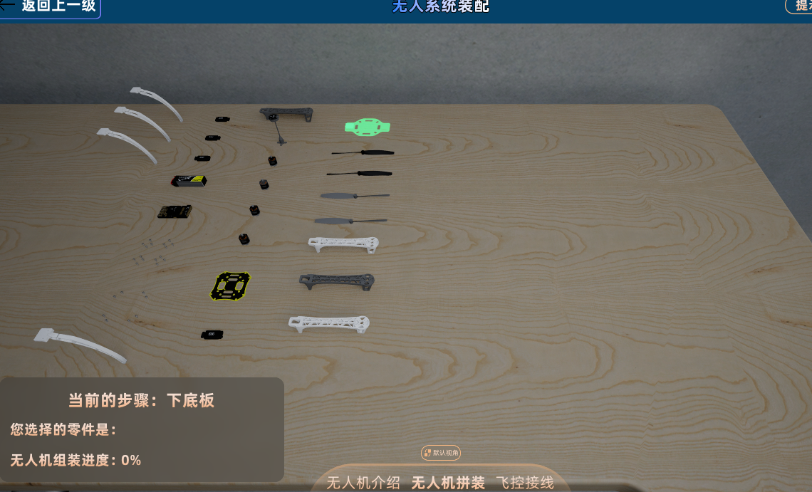
After entering the "Drone Assembly" scene, the interface typically includes the following elements:
- Installation Step Prompt: Displays the name of the part to be installed in the current step and operation tips.
- Parts to be Installed Area: Displays the parts needed for the current or subsequent steps on the desktop.
- Body Installation Area: Displays the drone main body and the currently available installation positions.
- Installation Progress Indicator: Displays the current assembly completion progress.
- Bottom Module Switch Buttons: Used to switch between Introduction, Assembly, and Wiring modules.
Parts that can be installed in the current step are highlighted in green; parts not yet ready for installation cannot be installed prematurely.
6.2 Standard Assembly Steps
Follow these steps to complete part installation:
- Observe the parts to be installed on the desktop and find the green-highlighted part.
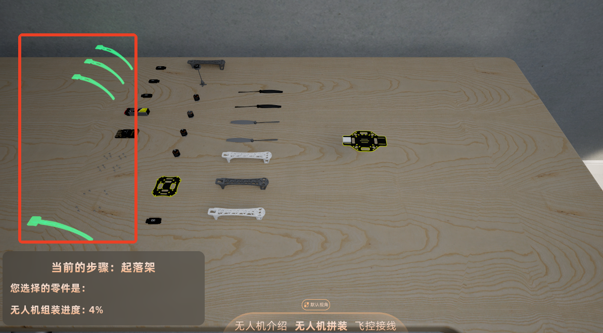
- Left-click the green-highlighted part to select it.
- Observe the synchronously highlighted installation position on the drone body.
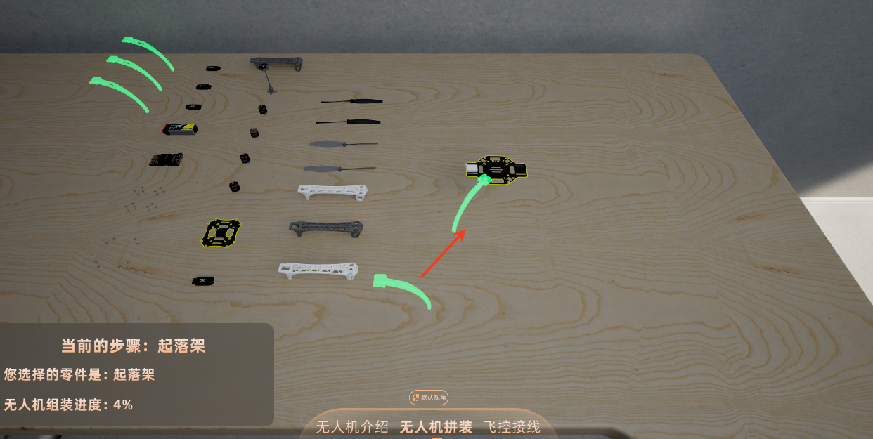
- Hold down the left mouse button and drag the part to the corresponding installation position.
- Release the left mouse button when the part is close to the correct position.
- The system automatically snaps the part into place, the part returns to its normal appearance, and the installation progress updates.
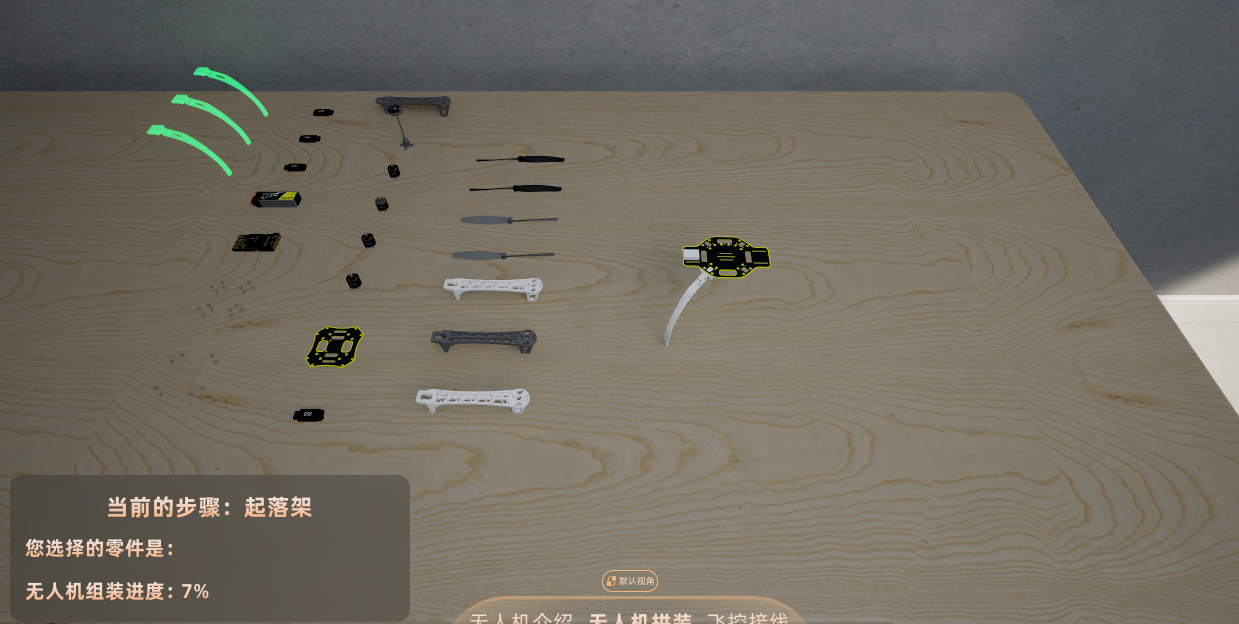
If the part is released before reaching the correct installation position, it will automatically return to its original position on the desktop, and the user needs to drag and install it again.
6.3 Installation Sequence Rules
The system follows a preset sequence for the assembly process; steps cannot be skipped.
| Operation Situation | System Feedback | Handling Method | Diagram |
| --- | --- | --- | --- |
| Click the part for the current step | Part and installation position display green highlight | Drag and install as prompted | 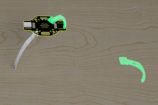 |
| Click a part not for the current step | "Cannot install the current part temporarily" prompt appears, incorrect position displays red highlight or part returns to original position | Return to the currently highlighted part and continue operation |
|
| Click a part not for the current step | "Cannot install the current part temporarily" prompt appears, incorrect position displays red highlight or part returns to original position | Return to the currently highlighted part and continue operation | 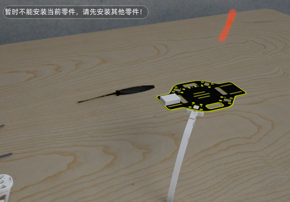 |
| Part installation successful | Part snaps into place, progress updates | Continue to the next step | |
|
| Part installation successful | Part snaps into place, progress updates | Continue to the next step | |
6.4 Motor Rotation Direction Setting
When installing a motor, the system handles the motor rotation direction according to the model's requirements. The setting method varies for different models.
F450 / Hexacopter:
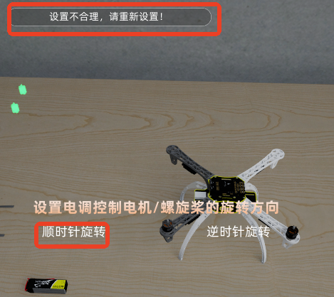
- After installing the first motor, the system displays a rotation direction setting window.
- The user needs to select "Clockwise (CW)" or "Counter-Clockwise (CCW)".
- After confirmation, a rotation effect corresponding to the direction is displayed above the motor.
- The direction of subsequent motors is automatically determined by the system based on the rule that adjacent motors have opposite directions.
- If the wrong direction is selected, the system displays an error prompt, and the user must correct it before continuing.
Propeller Direction:
- When installing a propeller, its rotation direction must match the corresponding motor.
- If the propeller direction does not match, the system displays an error prompt.
- The user should re-select the correct propeller based on the rotation effect above the motor and the system prompt.
DJI S1000:
- The motor rotation direction for the S1000 is a fixed pattern; no direction selection window appears during installation.
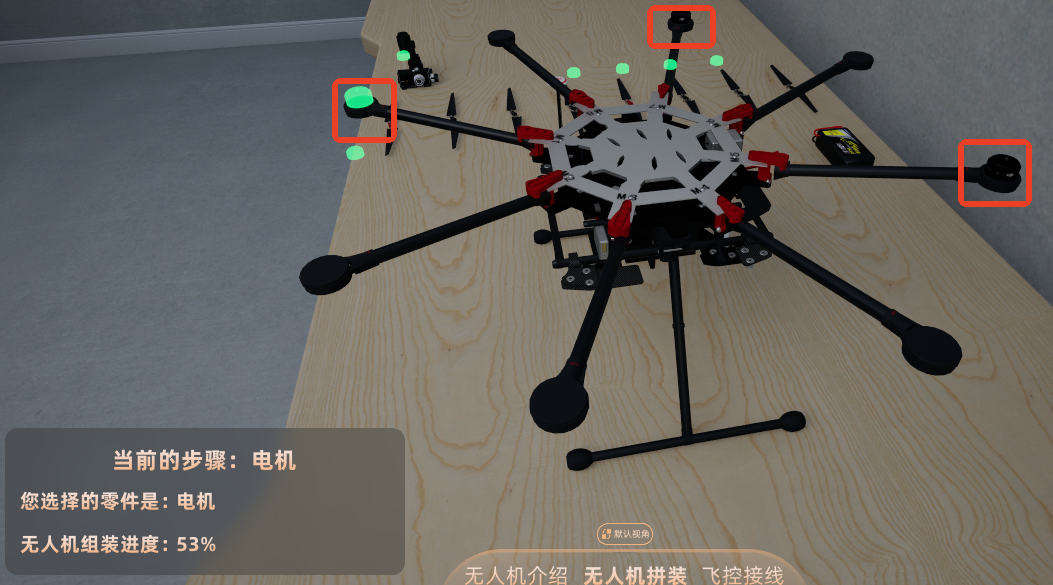
- M1/M3/M5/M7 are Counter-Clockwise (CCW).
- M2/M4/M6/M8 are Clockwise (CW).
- The arms have CW/CCW markings, and the installation positions have M1 to M8 number markings.
- During installation, priority should be given to confirming the number, then confirming the rotation direction.
6.5 Assembly Complete
After all parts are installed, the system displays a "Congratulations on completing the drone assembly" prompt.
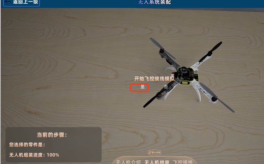
| Option | System Behavior |
|---|---|
| Yes | Directly jump to the "Flight Controller Wiring" module to continue wiring training |
| No | Stay on the current page, can switch via the bottom module buttons |
It is recommended to enter the flight controller wiring module immediately after assembly to maintain continuity in structural and motor number memory.
7 Flight Controller Wiring Module
The flight controller wiring module is used to learn the connection relationships between motors, ESCs, and the flight controller, and to verify whether the wiring direction is correct through system feedback.
7.1 Scene Initial State
Upon entering the "Flight Controller Wiring" scene, the interface typically displays the following:
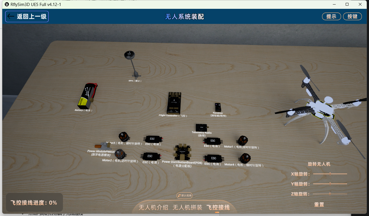 - Wiring progress indicator.
- An assembled drone displayed with auto-rotation.
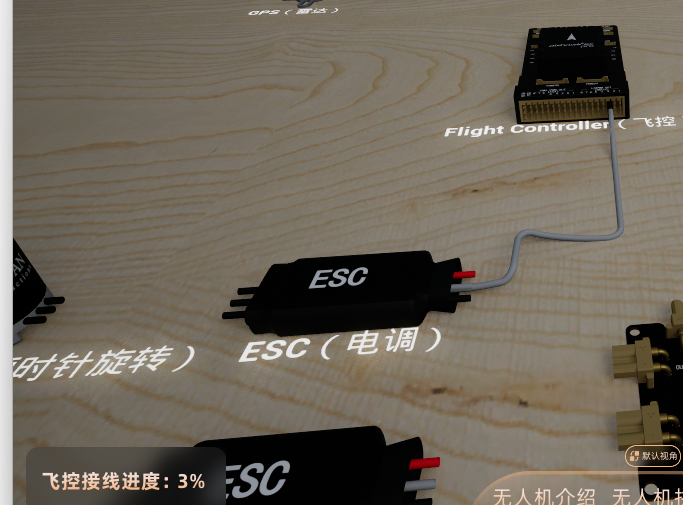
- Wiring components on the desktop, such as the flight controller, ESCs, and connection terminals.
- Interactive terminals and their highlight prompts.
- Wiring progress indicator.
- An assembled drone displayed with auto-rotation.
- Wiring components on the desktop, such as the flight controller, ESCs, and connection terminals.
- Interactive terminals and their highlight prompts.
7.2 Standard Wiring Steps
Flight controller wiring is completed using a "select start point, then select end point" method.
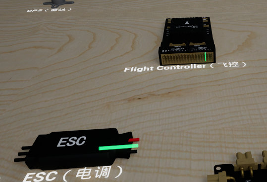
Step 1: Select the Starting Terminal
- Click on a terminal on a component.
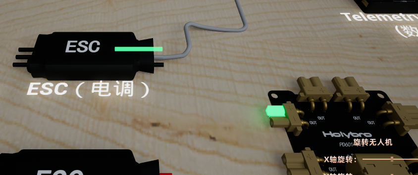
- The terminal becomes highlighted.
- Connectable target terminals begin to highlight or flash.
-
The corresponding component on the drone is highlighted synchronously.
 Step 2: Connect the Target Terminal
 -
Click on the flashing target terminal.
- The system generates a connection line between the two terminals.
- The corresponding component on the drone returns to its normal appearance.
-
The wiring progress is updated.
 Cancel Selection:
 -
Click the selected starting terminal again to cancel the current selection.
- Double-click on an empty area of the desktop to also cancel the current selection.
- After cancellation, all highlights and flashing effects disappear, and the system returns to a waiting state.
Zoom In:
- Double-click a terminal to zoom the view centered on that terminal for detailed inspection.
- After zooming in, you can continue to use camera rotation, zoom, and pan operations to adjust the viewing angle.
7.3 Wiring Correctness Determination
The system automatically verifies whether each set of wiring is reasonable.
When wiring is correct:
- Clockwise motors are connected to the motor, ESC, and flight controller in a non-crossing manner.
- Counter-clockwise motors are connected to the motor, ESC, and flight controller in a crossing manner.
- After wiring is complete, a rotation effect in the corresponding direction is displayed above the motor.
- The wiring progress is updated.
When wiring is incorrect:
- The system displays a prompt: "Connection is not reasonable, please reconnect."
- A rotation effect in the wrong direction or an error prompt effect is displayed.
- The current incorrect connection is automatically undone.
- The prompt includes a flight controller wiring diagram, which the user can refer to for reconnection.
Note: In actual operation, the system's currently highlighted target terminals, model numbers, and wiring diagram should be used as the standard.
7.4 Undo Connection
To undo a completed connection, press Ctrl+Z.
| Operation | Effect |
|---|---|
| Press Ctrl+Z once | Undo the most recently completed set of connections |
| Press Ctrl+Z repeatedly | Undo connections one by one, from newest to oldest |
After undoing, to reconnect, simply follow the standard wiring steps to reselect the terminals.
8 Progress Saving and Module Switching
During assembly or wiring, users can switch to other modules using the bottom module buttons. The system will prompt a save confirmation upon switching.
| Current Operation | Select "Yes" to Save | Select "No" to Not Save |
|---|---|---|
| Switching modules during assembly | Retain installed parts and installation progress upon return | Progress is reset to zero upon return, returning to the initial assembly state |
| Switching modules during wiring | Retain completed connections and wiring progress upon return | All connections are restored to an unconnected state upon return |
It is recommended to save in the following situations:
- After completing multiple part installation steps.
- After completing a portion of the wiring and needing to temporarily view the introduction module.
- During a teaching demonstration when needing to temporarily leave the current module.
It is recommended not to save in the following situations:
- There are many errors in the current steps and you wish to start over.
- An instructor needs to restore the initial state for a demonstration.
- A user wants to re-practice the entire process.
9 Shortcuts and Operations Overview
| Shortcut/Operation | Function | Applicable Scenario |
|---|---|---|
| Mouse Left Button + Drag | Rotate view | All scenes |
| Mouse Middle Button Wheel | Zoom view | All scenes |
| Mouse Right Button + Drag | Pan view | All scenes |
| Mouse Left Button Click | Select a part or terminal | Introduction, assembly, wiring scenes |
| Mouse Left Button Drag | Drag a part to its installation position | Assembly scene |
| Mouse Middle Button + Drag | Rotate to view the selected part | Exploded state in the introduction module |
| Double-click Terminal | Zoom in to view terminal details | Wiring scene |
| Double-click Empty Area | Cancel terminal selection | Wiring scene |
| Ctrl+Z | Undo the most recent set of connections | Wiring scene |
10 Common Issues and Troubleshooting
| Issue Phenomenon | Possible Cause | Solution |
|---|---|---|
| Clicking "Flight Training" or "Drone Design" does not enter | Module is still under development | Use the currently available "Unmanned System Assembly" module |
| View is off the model, cannot find the drone | Excessive camera rotation, zoom, or pan | Click the "Restore Default View" button |
| Part returns to the desktop after being dragged | Not dragged to the correct installation position, or it is not the installation step for that part | Observe the green highlight prompt and re-drag the part for the current step |
| Prompt "Cannot install" after clicking a part | The part does not belong to the current installation step | Follow the installation step prompts to select the green highlighted part |
| Prompt error after selecting motor direction | The selected CW/CCW direction does not conform to the current model's rules | Re-select the correct direction based on the system prompt |
| Prompt direction inconsistency during propeller installation | Propeller direction does not match the corresponding motor direction | View the motor rotation effect and select a propeller with the matching direction |
| Prompt "Connection is not reasonable" after wiring | Incorrect selection of starting or target terminal, or the wiring crossing method does not match the motor direction | View the highlighted terminals and wiring diagram, then reconnect |
| Want to undo a just-completed connection | Incorrect wiring target selection or need to re-demonstrate | Press Ctrl+Z to undo the most recent set of connections |
| Progress lost after switching modules | Selected "No" to not save when switching | Select "Yes" to save before the next switch, or redo the current process |
| Video window obscures the model | Video window position or size is inappropriate | Drag the title bar to move the window, or drag the edge to resize the window |