RflySim PHM - Fault Injection and Health Assessment Interface Library
The RflySim PHM (Prognostics and Health Management) library provides a comprehensive suite of tools for fault injection and health assessment, supporting modeling, injection, and evaluation of various hardware faults on UAVs, enabling validation of flight control system fault tolerance and fault-handling performance.
Module List
Power System Faults
| Module | Function Description |
|---|---|
| Motor Fault | Motor fault injection, supporting fault modes such as reduced motor efficiency, stalling, and complete shutdown |
| Prop Fault | Propeller fault injection, supporting fault modes such as blade damage, detachment, and efficiency degradation |
| Battery Fault | Battery fault injection, supporting fault modes such as voltage drop, capacity decay, and increased internal resistance |
Environmental Disturbance Faults
| Module | Function Description |
|---|---|
| Wind Fault | Wind disturbance fault injection, supporting environmental disturbances such as gusts, turbulence, and wind shear |
| Load Fault | Load fault injection, supporting fault modes such as sudden load changes, center-of-gravity shift, and payload detachment |
Sensor Faults
| Module | Function Description |
|---|---|
| GPS Fault | GPS fault injection, supporting fault modes such as positioning drift, signal loss, and reduced accuracy |
| Sensor Fault | General-purpose sensor fault injection, supporting faults in IMU, magnetometer, barometer, and other sensors |
Utility Modules
| Module | Function Description |
|---|---|
| PHM 6DOF | Six-degree-of-freedom dynamics block connected to the PHM fault-model bus for state propagation under injected faults |
| Fault Params Extract | Fault parameter extraction module, used to extract and parse fault parameters from fault configuration files |
Fault Type Descriptions
Power System Faults
| Fault Type | Typical Manifestations | Application Scenarios |
|---|---|---|
| Motor efficiency degradation | Reduced rotational speed, slower response | Motor aging, thermal protection activation |
| Motor stalling | Complete loss of thrust | Mechanical failure, foreign object blockage |
| Propeller damage | Reduced thrust, increased vibration | Blade impact, fatigue cracks |
| Battery voltage drop | Insufficient power, premature landing | Low-temperature operation, deep discharge |
Environmental Disturbance Faults
| Fault Type | Typical Manifestations | Application Scenarios |
|---|---|---|
| Gust disturbance | Attitude oscillation, position deviation | Strong wind conditions, urban wind fields |
| Turbulence disturbance | Random vibration, control difficulty | Complex terrain, wake regions |
| Sudden load change | Center-of-gravity shift, reduced control margin | Payload release, suspended payload swing |
Sensor Faults
| Fault Type | Typical Manifestations | Application Scenarios |
|---|---|---|
| GPS drift | Increased positioning error, navigation failure | Signal obstruction, multipath effects |
| IMU drift | Attitude estimation bias, spin divergence | Temperature drift, vibration interference |
| Magnetometer interference | Yaw angle jumps, calibration failure | Electromagnetic interference, hard-iron effects |
Application Scenarios
Fault-Tolerant Control Algorithm Validation
- Fault Detection: Validate the flight control system’s ability to detect various faults and its response speed |
- Control Reconfiguration: Test the system’s ability to reconfigure control and implement degraded control after fault occurrence |
- Safe Landing: Validate emergency landing strategies under severe fault conditions |
Sensor Fusion Algorithm Testing
- Fault Identification: Test the capability of multi-sensor fusion to identify single-sensor faults |
- Weight Adjustment: Validate adaptive sensor weight adjustment under fault conditions |
- State Estimation: Evaluate state estimation accuracy under fault conditions |
Flight Safety Assessment
- Fault Coverage: Assess the flight control system’s coverage capability across different fault modes |
- Fault Propagation: Analyze fault propagation paths and impact scope within the system |
- Safety Boundary: Determine safe flight boundaries under various fault conditions |
Usage Considerations
Fault Parameter Configuration
- Fault Intensity: Fault intensity parameters must be set within a reasonable range; excessively large values may cause simulation divergence or crash |
- Gradual Injection: It is recommended to inject faults gradually to avoid simulation instability caused by instantaneous abrupt changes |
- Injection Timing: Select appropriate fault injection timing to avoid injecting severe faults during critical control phases (e.g., takeoff or landing) |
- Parameter Consistency: Ensure fault parameters match the corresponding fault type to avoid incompatible parameter combinations |
Simulation Safety
- Boundary Protection: Set reasonable flight boundaries; automatically terminate the simulation if the UAV’s state exceeds safe limits |
- Fault Recovery: When designing fault recovery tests, ensure sufficient time and space for recovery |
- Multiple Faults: Exercise caution when testing simultaneous multiple faults to avoid unpredictable interaction effects |
- Logging: Enable detailed simulation logging for post-analysis and fault reproduction |
Interaction with Flight Control System
- Message Frequency: The frequency of fault injection messages must match the flight control processing cycle to avoid message accumulation or loss |
- Protocol Compatibility: Ensure fault parameter formats are consistent with those expected by the flight control system to prevent parsing errors |
- Permission Management: Thoroughly validate fault injection logic in simulation before conducting real-flight tests |
- Emergency Stop: Ensure a reliable emergency stop mechanism is available during real-flight tests to immediately take over control in case of fault loss of control |
Fault Modeling Principles
The PHM fault model divides fault injection locations into actuators, environment, payload, sensors, and state output links. The modeling goal is not simply to cause simulation anomalies, but to ensure faults are observable by the controller, diagnostic algorithms, and health assessment modules.
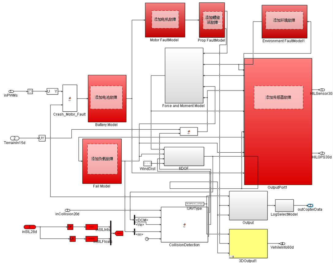
Motion Model Injection Relationships
Except for sensors, most faults ultimately enter the rigid-body motion model through total force, total torque, mass, inertia, or external disturbances.
| Fault Category | Primary Influenced Quantities |
|---|---|
| Power System Faults | Total thrust F, three-axis torque tau |
| Environmental Faults | External force, external torque, relative wind speed and world-frame velocity |
| Load Faults | Mass m, inertia matrix J, additional torque |
| Sensor Faults | Scale factor, constant bias, impact, delay, random walk noise |
Power System Faults
| Fault Type | Injection Location | Typical Manifestations | Key Parameters |
|---|---|---|---|
| Battery Fault | Voltage, current, remaining capacity model | Voltage drop, insufficient power, reduced endurance | Internal resistance, capacity, SOC, discharge rate |
| ESC Fault | Between PWM and motor command | Single-channel output saturation, delay, failure | Gain, bias, dead zone, response time |
| Motor Fault | Motor speed and thrust model | Reduced thrust, stalling, slower response | Thrust coefficient, speed limit, time constant |
| Propeller Fault | Thrust/torque generation stage | Reduced propeller efficiency, imbalance, additional vibration | Efficiency coefficient, damage ratio, torque deviation |
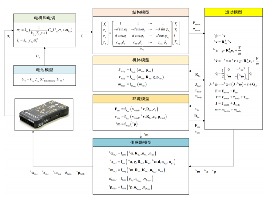
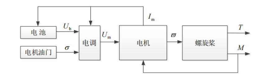
The power system can be modeled according to the signal chain of battery, ESC, motor, and propeller:
| Sub-model | Relationship | Description |
|---|---|---|
| Battery | U_b = k_Ub * f_Ub(C_dch_effective, U_b0) |
k_Ub is the battery fault coefficient, affecting output voltage |
| ESC | U_m = k_Um * sigma * U_b |
sigma is the normalized throttle, k_Um is the ESC fault coefficient |
| Motor | omega = k_omega / (k_Tm * T_m * s + 1) * omega_ss |
Describes response speed and execution efficiency faults |
| Propeller | T = k_CT * c_T * omega^2, M = c_M/T * T |
k_CT changes thrust efficiency |
Environmental and Load Faults
| Fault Type | Modeling Method | Impact |
|---|---|---|
| Wind Fault | Add external force in geographic or body frame | Position drift, velocity error, increased attitude compensation |
| Wind Torque Fault | Add additional roll/pitch/yaw torque | Attitude oscillation, long-term control bias |
| Real-time Obstacle | Inject obstacle via UE or collision model | Path planning, obstacle avoidance, and collision detection |
| Mass Change | Modify mass parameter | Simulate payload release, load change, battery replacement |
| Moment of Inertia Change | Modify inertia matrix | Affects attitude response and angular acceleration |
| Center of Gravity Shift | Modify center of gravity or add additional torque | Produces sustained attitude deviation and control compensation |
Load faults should simultaneously update gravity, inertia, and moment arm; otherwise, inconsistent dynamic results will occur.
The environmental wind field can be composed of atmospheric turbulence, constant wind, wind shear, and gusts:
The drag and additional torque caused by wind disturbance can be written as:
Where p_wind is the position vector of the wind force application point in the body frame. Real-time obstacles are typically dynamically instantiated by the 3D engine at the fault trigger time and can be superimposed with the wind field to construct complex mission environments.
Load mass shift changes the inertia matrix and introduces additional torque:
Sensor Faults
| Sensor | Common Faults | Observed Manifestations |
|---|---|---|
| Gyroscope | Bias, increased noise, drift, stalling | Attitude estimation drift, abnormal angular velocity |
| Accelerometer | Bias, scale factor, impact anomaly | Abnormal attitude and velocity estimation |
| Magnetometer | Bias, interference, loss of lock | Yaw angle jump or long-term deviation |
| Barometer | Bias, random walk, step change | Incorrect altitude estimation |
| GPS | Loss of satellites, delay, noise, spoofing, position jump | Abnormal position and velocity estimation |
Sensor faults are typically injected before SensorOutput or HIL output. After injection, ensure that data type, unit, and sampling frequency still meet the flight control input requirements.
Common sensor faults can be uniformly represented as the measured quantity after passing through scale factor, constant bias, drift, and noise from the true quantity:
| Sensor | Simplified Model | Main Parameters |
|---|---|---|
| Gyroscope | omega_m = k_g * (omega + c_g) + b_g + n_g |
Scale factor, constant bias, drift, white noise |
| Accelerometer | a_m = k_a * (a + lever_arm_terms - gravity_terms) + b_a + n_a |
Scale factor, lever arm terms, drift, noise |
| Magnetometer | m_m = k_m * (R_be * m_e + c_m) + b_m + n_m |
Geomagnetic vector, installation attitude, bias |
| Barometer | d_baro = -k_baro * (p_z + c_baro) + b_baro + n_baro |
Altitude bias, scale factor, drift |
| GPS | p_gps = k_gps * (p + c_gps) + b_gps + n_gps |
Position bias, scale factor, random walk |
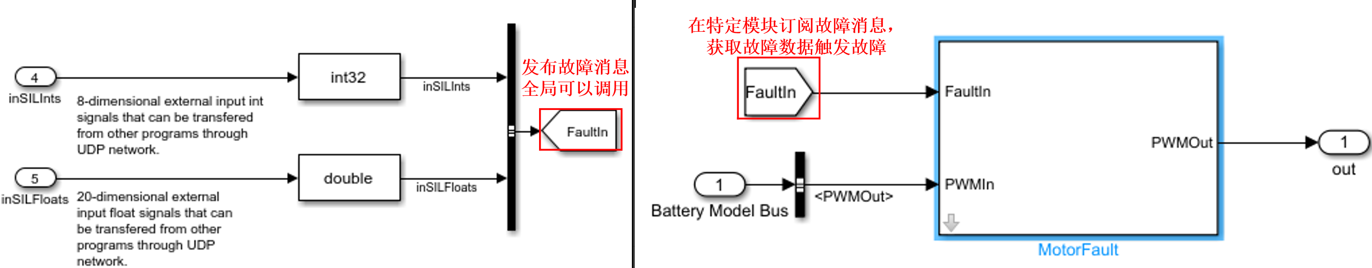
Fault Injection Protocol
The PHM module receives fault identifiers and fault parameters via inSILInts and inSILFloats. Each fault uses a unique FaultID to locate the type, and parameters are written into a floating-point array according to the fault module convention.
| Variable Name | Type | Length | Description |
|---|---|---|---|
inSILInts |
int32[] |
8 | Fault identifier, used for type selection and channel localization |
inSILFloats |
float32[] |
20 | Fault parameters, used to set fault intensity, ratio, noise, or wind speed, etc. |
| FaultID | Fault Type | Fault Parameters |
|---|---|---|
123450 |
Motor efficiency fault | Efficiency ratio for motors 1 to x, range 0-1 |
123451 |
Propeller fault | Efficiency ratio for propellers 1 to x, range 0-1 |
123452 |
Battery failure fault | None |
123453 |
Low voltage fault | Voltage failure ratio, range 0-1 |
123454 |
Low battery fault | Battery failure ratio, range 0-1 |
123455 |
Load fault | Weight leakage ratio, range 0-1 |
123456 |
Load drift fault | Weight leakage ratio and x/y/z leakage factors, range 0-1 |
123457 |
Load leakage fault | Weight leakage ratio and leakage factor, range 0-1 |
123458 |
Constant wind fault | Wind speed on x/y/z axes |
123459 |
Gust wind fault | Gust intensity and arrival time |
123540 |
Turbulence wind fault | Turbulence intensity |
123541 |
Shear wind fault | Shear wind intensity |
123542 |
Accelerometer noise interference | Noise gain |
123543 |
Gyroscope noise interference | Noise gain |
123544 |
Magnetometer noise interference | Noise gain |
123545 |
Barometer noise interference | Noise gain |
123546 |
GPS fault | Noise gain, 3D mode, and number of satellites |
Single fault injection example: 4 motors with efficiencies of 1, 0.8, 0.5, 1.
Multi-fault joint injection example: Inject motor efficiency fault and accelerometer noise fault simultaneously.
Fault Parameter Management
| Parameter | Description |
|---|---|
faultType |
Fault category or module number |
startTime |
Fault start time |
duration |
Fault duration |
severity |
Fault intensity or damage ratio |
channel |
Actuator or sensor channel |
bias |
Additive bias |
scale |
Multiplicative scale |
noiseStd |
Noise standard deviation |
When creating a PHM dataset, it is recommended to record fault parameters, flight controller logs, ground truth states, control inputs, and sensor outputs simultaneously. Saving only flight controller logs is usually insufficient to replay the fault location and intensity.
Module Page Index
| Topic | Page |
|---|---|
| Battery fault | Battery Fault |
| Motor fault | Motor Fault |
| Propeller fault | Prop Fault |
| Wind and environmental fault | Wind Fault |
| Load fault | Load Fault |
| GPS fault | GPS Fault |
| General sensor fault | Sensor Fault |
| PHM six-degree-of-freedom model | PHM 6DOF |
| Fault parameter extraction | Fault Params Extract |
Related Resources
- PX4 Official Documentation - Fault Detection
- RflySim PHM Development Guide
- A Survey on UAV Fault-Tolerant Control
- IEEE PHM Standards
Note: This document serves as the index for the RflySim PHM library. For detailed usage instructions for each module, please refer to the corresponding standalone module documentation pages.