InputRcCali Module Documentation
Toolbox: RflySim APIs
Introduction
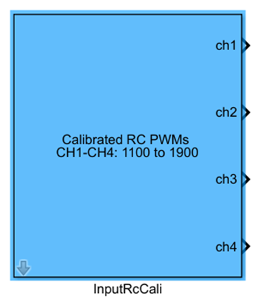
One-sentence Description: Calibrates and maps the raw PWM signals from the remote controller input, standardizing the output to the 1100–1900 range.
This module is a tool within the RflySim APIs library, specifically designed for remote controller input calibration. It serves the standardization of remote controller inputs in PX4 flight controller simulations, commonly used in manual remote control simulation scenarios, to provide calibrated remote channel data that conforms to the PX4 standard range for subsequent flight control algorithms. Typically used in conjunction with remote controller input acquisition modules or simulation input modules, it outputs four calibrated standard control channels, which can be directly connected to the PX4 flight controller’s remote input interface. Combined with the CopterSim physical simulation engine and RflySim3D visualization engine, it enables manual remote control simulation validation for drones.
Port Descriptions
Input Ports (Inputs)
This module has no input ports.
Output Ports (Outputs)
| Port Name | Data Type | Dimension | Description |
|---|---|---|---|
CH1 |
double |
1×1 |
Calibrated roll channel PWM value, range 1100–1900; 1900 indicates maximum rightward flight |
CH2 |
double |
1×1 |
Calibrated pitch channel PWM value, range 1100–1900; 1900 indicates maximum downward flight |
CH3 |
double |
1×1 |
Calibrated throttle channel PWM value, range 1100–1900; 1900 indicates maximum upward flight |
CH4 |
double |
1×1 |
Calibrated yaw channel PWM value, range 1100–1900; 1900 indicates maximum rightward rotation |
Parameter Configuration (Parameters)
The following parameters can be configured in the Mask dialog box opened by double-clicking the module:
| Parameter Name | Type | Default Value | Optional Values / Range | Description |
|---|---|---|---|---|
Sample Time(s) |
double |
0.01 |
>0 |
Module sampling time, in seconds |
Parameter Setting Description
Sample Time(s)
This parameter specifies the sampling step size of the module, determining the update frequency of the calibrated remote controller data. Typically, it should be set to match the flight controller loop period.
Module Characteristics (Block Characteristics)
| Characteristic | Value |
|---|---|
| Supported Data Types | double, single |
| Direct Feedthrough | No |
| Sample Time | Discrete |
| Code Generation Support | No |
Data Communication Protocol
This module does not involve network communication.
Related Modules
| Module Name | Description |
|---|---|
JoystickInput |
Reads input data from physical joystick devices, providing raw input sources for remote controller simulation |
ReadJoystickCal |
Reads calibrated joystick input data |
InputRcRaw |
Outputs uncalibrated raw remote controller PWM data |
Usage Example
For related usage examples, please refer to the following path:
Please refer to
Readme.pdfin the above path for complete example descriptions and operational steps.
Notes and Common Issues
- Initialization Sequence: This module relies on the underlying remote controller input driver of the RflySim platform. It must be run only after RflySim Vision has completed hardware connection or simulation environment initialization. Attempting to read remote controller data before platform initialization will result in fixed or zero-valued outputs.
- Sample Time Matching: The
Sample Time(s)parameter of this module must match the sampling step size of the entire flight control model. Mismatched sample times will cause delayed updates of remote controller data, resulting in sluggish control command responses. - Calibration Range Note: The module outputs are mapped by default to the standard PWM range of 1100–1900. If your flight control code uses a different control input range, additional scaling conversion must be added after the module output before connecting to the flight controller interface; the output should not be connected directly.
- Channel Direction Note: The channel directions of this module follow RflySim platform conventions. If using a custom flight control system, verify whether the channel direction definitions match: CH1 at 1900 corresponds to maximum right roll, CH2 at 1900 to maximum downward pitch, CH3 at 1900 to maximum throttle, and CH4 at 1900 to maximum right yaw. If directions are reversed, inversion processing must be added.
- No Remote Controller Attached: If no physical remote controller is connected, this module will output zero or invalid values. During simulation debugging, signal source modules can be used to generate simulated inputs as substitutes; this module should not be left unused as a control input when no remote controller is connected.
Change Log
v4.0.0(2023-01-01): Initial release. Provides remote controller PWM data calibration and mapping functionality, supporting calibration of raw remote channel data to the 1100–1900 range.