SensorFault Module Documentation
Toolbox: RflySim PHM
Introduction
One-sentence description: This module provides multi-type sensor fault injection capabilities for UAV PHM (Prognostics and Health Management) simulation, enabling the addition of specified fault effects to raw sensor measurement data based on input fault configuration.
This module belongs to the RflySim PHM toolchain and is primarily used for semi-physical simulation validation of UAV fault diagnosis and sensor health management algorithms. It supports injecting various fault types—including offset, stuck, and gain deviation faults—into commonly used UAV flight control sensors such as barometers, GPS receivers, gyroscopes, and accelerometers. The module receives raw ideal sensor measurement data output from the PX4 flight controller, as well as external input specifying fault types and fault parameters, and outputs sensor data with injected faults for subsequent processing by flight control or PHM algorithms.
Within the RflySim simulation chain, this module resides at the downstream end of the sensor simulation chain and can interact with CopterSim’s dynamics simulation and RflySim3D’s visualization environment, providing a controllable and reproducible sensor fault simulation environment for PHM algorithm development—without requiring physical hardware to validate various sensor fault scenarios.
Port Descriptions
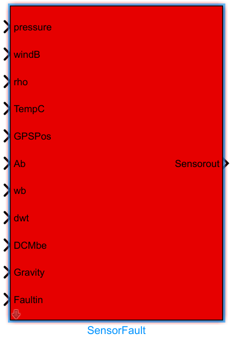
Input Ports (Inputs)
| Port Name | Data Type | Dimension | Description |
|---|---|---|---|
pressure |
double |
1×1 |
Raw atmospheric pressure input |
windB |
double |
1×3 |
Wind velocity input in body-fixed coordinate frame |
rho |
double |
1×1 |
Air density input |
TempC |
double |
1×1 |
Atmospheric temperature input, in degrees Celsius |
GPSPos |
double |
1×3 |
Raw GPS position input |
Ab |
double |
1×3 |
Actual body-axis acceleration input, in units consistent with configured units |
wb |
double |
1×3 |
Body-axis angular rate input, in radians/second |
dwt |
double |
1×3 |
Body-axis angular acceleration input, in radians/second² |
DCMbe |
double |
3×3 |
Direction cosine matrix for transforming forces due to payload motion into the UAV coordinate frame |
Gravity |
double |
1×1 |
Gravitational acceleration input |
FaultIn |
double |
Arbitrary | Fault input containing fault type and fault parameter information |
Output Ports (Outputs)
| Port Name | Data Type | Dimension | Description |
|---|---|---|---|
Sensorout |
Bus |
- | Sensor output bus after fault injection, encapsulating UAV acceleration, angular rate, barometric pressure, GPS, and other sensor data |
Parameter Configuration (Parameters)
This module has no configurable parameters [To be confirmed].
Parameter Setting Instructions
None.
Module Characteristics (Block Characteristics)
| Characteristic | Value |
|---|---|
| Supported Data Types | double, single |
| Direct Feedthrough | Yes |
| Sample Time | Inherited |
| Code Generation Support | No |
Data Communication Protocol
This module does not involve network communication.
Related Modules
| Module Name | Description |
|---|---|
ActuatorFault |
PHM module for generating UAV actuator fault signals |
PropellerFault |
PHM module for generating UAV propeller fault signals |
VehicleFaultInjector |
PHM module for unified management of multi-fault injection in UAVs |
Notes and Common Issues
- Initialization Order: This module relies on upstream raw sensor signals that have already undergone coordinate transformation and unit conversion. It must be updated only after the aircraft dynamics model and coordinate transformation modules have completed initialization; otherwise, abnormal output values may occur.
- Fault Parameter Format Matching: The fault input
FaultInmust strictly match the format required by the module. The positions of parameters corresponding to different sensor faults must align with their definitions—for example, the fault value for barometer faults must be placed as the first element of the parameter vector; otherwise, the injected fault results will not match expectations. - Sample Time Matching: This module must maintain consistent sample time with upstream sensor input modules. When configured for fixed-step simulation, the module’s sample time must be an integer multiple of the simulation step size to avoid timing misalignment in fault injection.
- Bus Output Matching: The output
Sensoroutis in Bus format. Downstream connected modules must use the corresponding Bus object definition. If signals are directly split, the port order must match the signal order of this module’s output bus; otherwise, incorrect sensor data may be read. - Validity of Direction Cosine Matrix: The input
DCMbemust be a valid, orthogonal, normalized direction cosine matrix. Passing a singular matrix will result in incorrect sensor output calculations after fault injection.
Changelog
v4.10(2024-07-25): Initial release of the SensorFault module, supporting common sensor fault injection functionality, including inner modulesNoiseFunandFaultParamsExtract.