Core Feature Video Demonstration
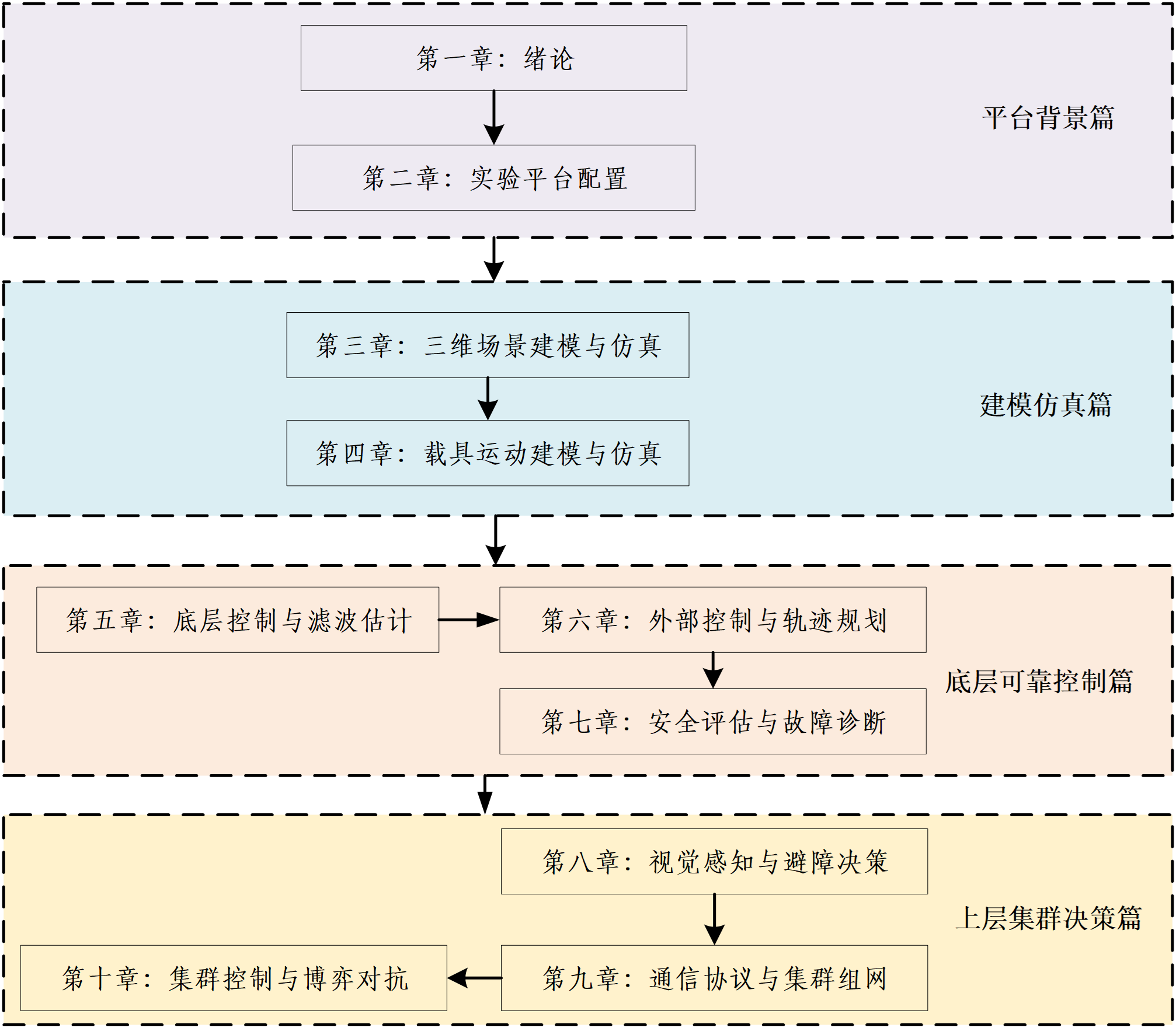
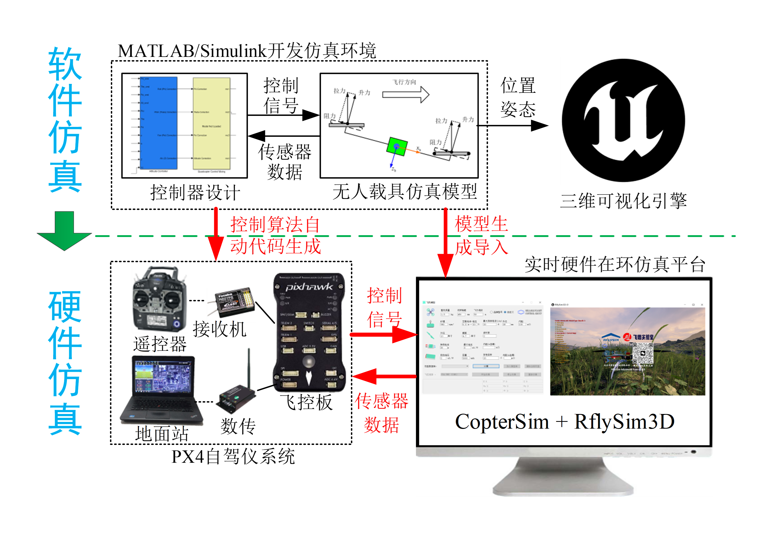
The RflySim toolchain is a high-reliability unmanned control system development, testing, and evaluation platform specifically designed for cutting-edge research fields including unmanned control system development, large-scale swarm coordination, and artificial intelligence vision. This toolchain adopts the Model-Based Design (MBD) concept and is built upon development tools such as Pixhawk/PX4, MATLAB/Simulink, Python/AI, and Linux/ROS, supporting algorithm development for 3D scene modeling of intelligent unmanned systems, vehicle dynamics modeling, low-level flight control, intelligent perception and planning, health assessment and fault diagnosis, and swarm game decision-making. Following the MBD workflow—through processes including unmanned system modeling, graphical modular controller design, automatic algorithm code generation, software-in-the-loop simulation, hardware-in-the-loop simulation, and rapid real-drone deployment—RflySim enables a swift transition from simulation to real hardware deployment. Meanwhile, we have divided the Intelligent Unmanned Swarm Systems course series into 10 chapters. These chapters progress step-by-step according to learning difficulty, helping users rapidly develop their own intelligent unmanned swarm systems from the inside out and from the bottom up. The relationship among chapters is shown below:
Chapter 1: Introduction
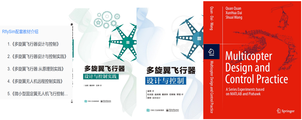
This chapter mainly explains the foundational knowledge of this toolchain, supporting textbooks, and hardware/software introductions. For details, see: Chapter 1 Toolchain Installation and Learning Methods
Chapter 2: Experimental Platform Configuration
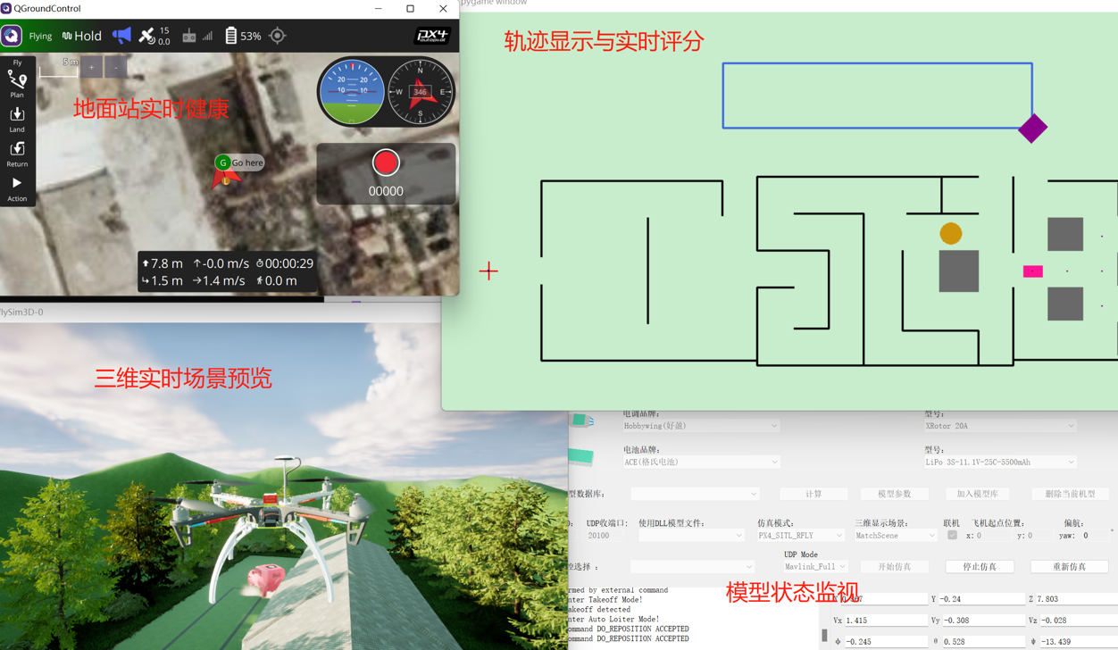
This chapter mainly explains toolchain module introductions, UI interface descriptions, key interface introductions, overall experimental workflow, and troubleshooting. For details, see: Chapter 2 Experimental Platform Configuration and Use
Chapter 3: 3D Scene Modeling and Simulation
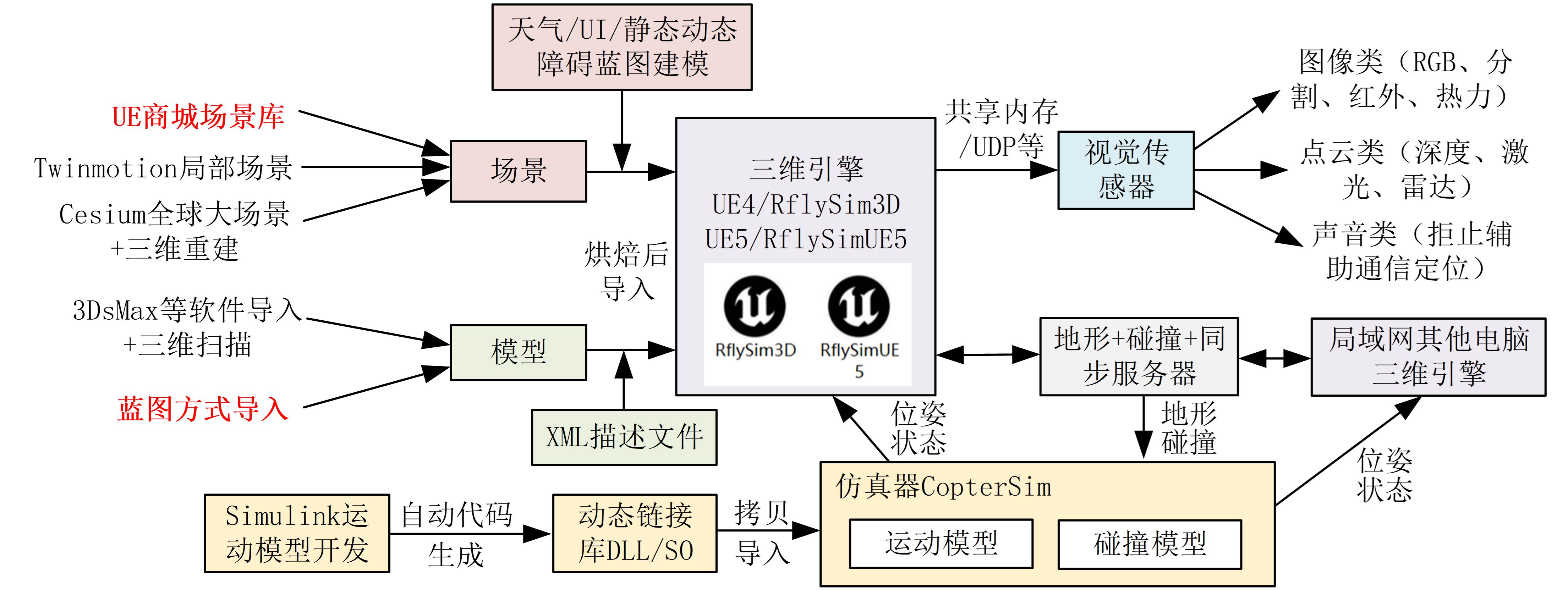
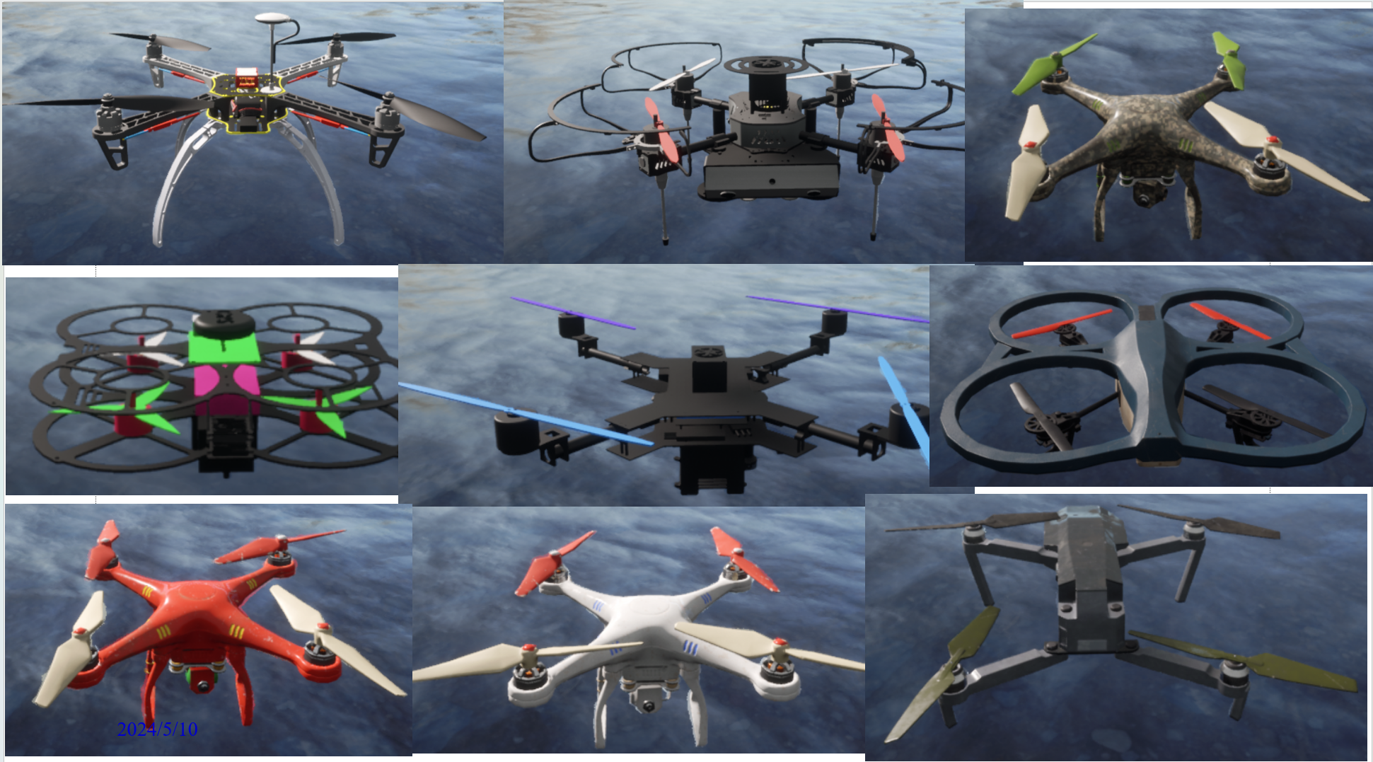
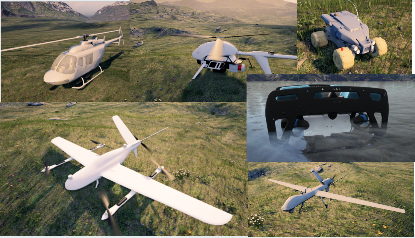
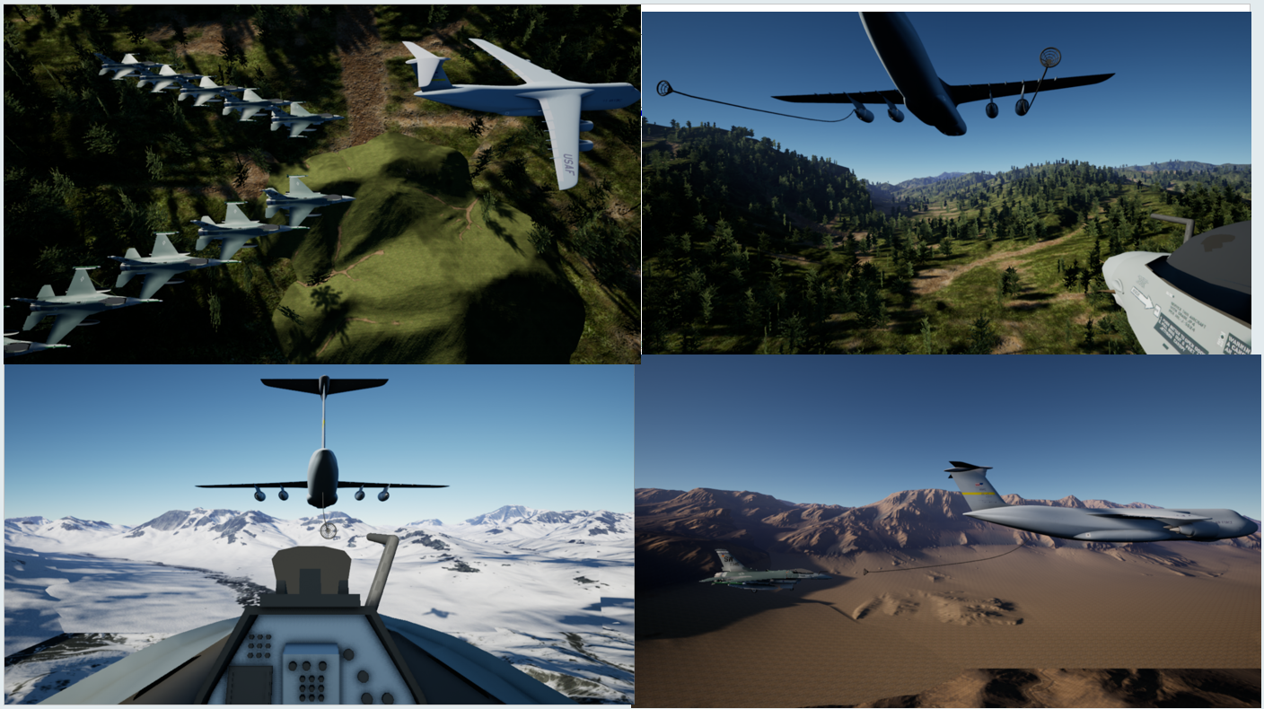
This chapter supports secondary development of 3D scene modeling, enabling rapid customization and import of your own aircraft and scenarios. External collision models reduce engine load, and the distributed architecture supports large-scale swarm simulation. For details, see: Chapter 3 3D Scene Modeling and Simulation

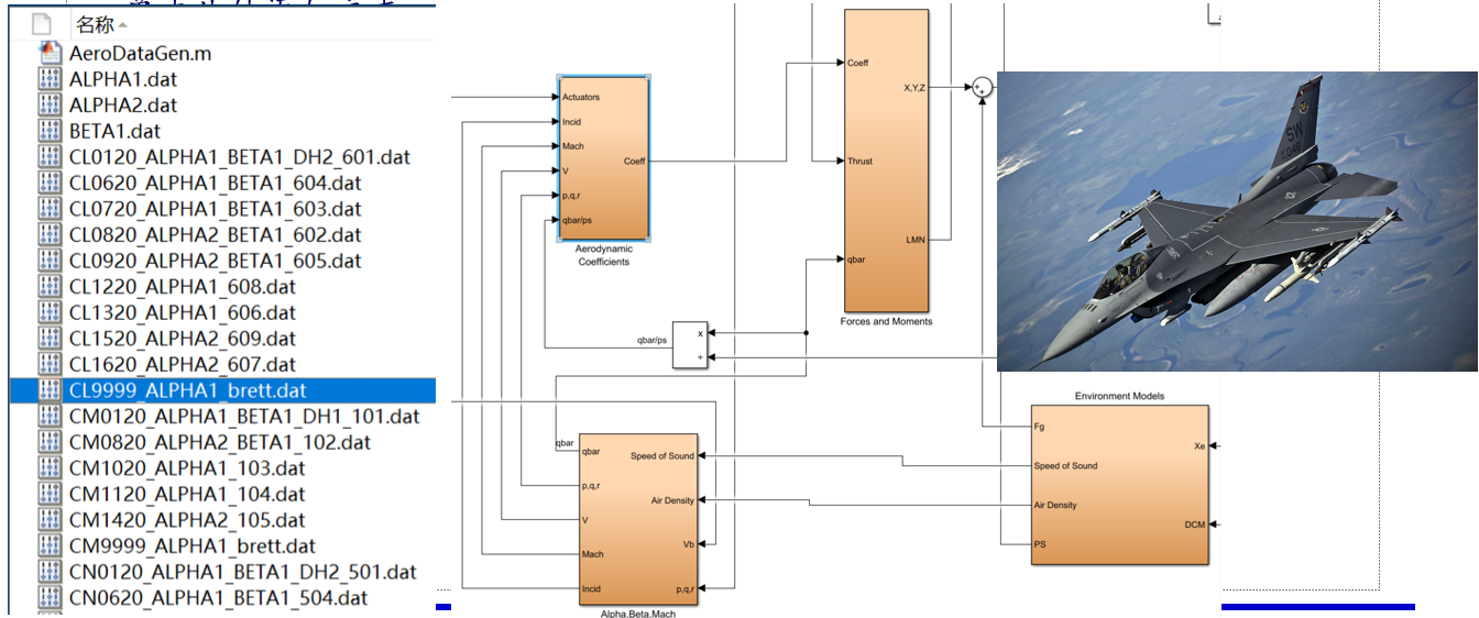
Chapter 4: Vehicle Motion Modeling and Simulation
In this chapter, under the given Simulink input-output interface framework, we quickly implement modeling for various types of vehicles, combine the identification and evaluation solutions provided by the toolchain to optimize and assess model accuracy, utilize automatic code generation technology to convert models into dynamic link libraries (DLLs), and then import them combined with PX4's native controllers or self-developed Simulink controllers to achieve hardware-in-the-loop simulation. For details, see: Chapter 4 Vehicle Motion Modeling and Simulation
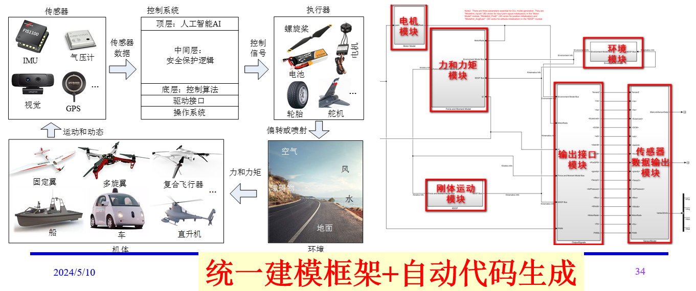
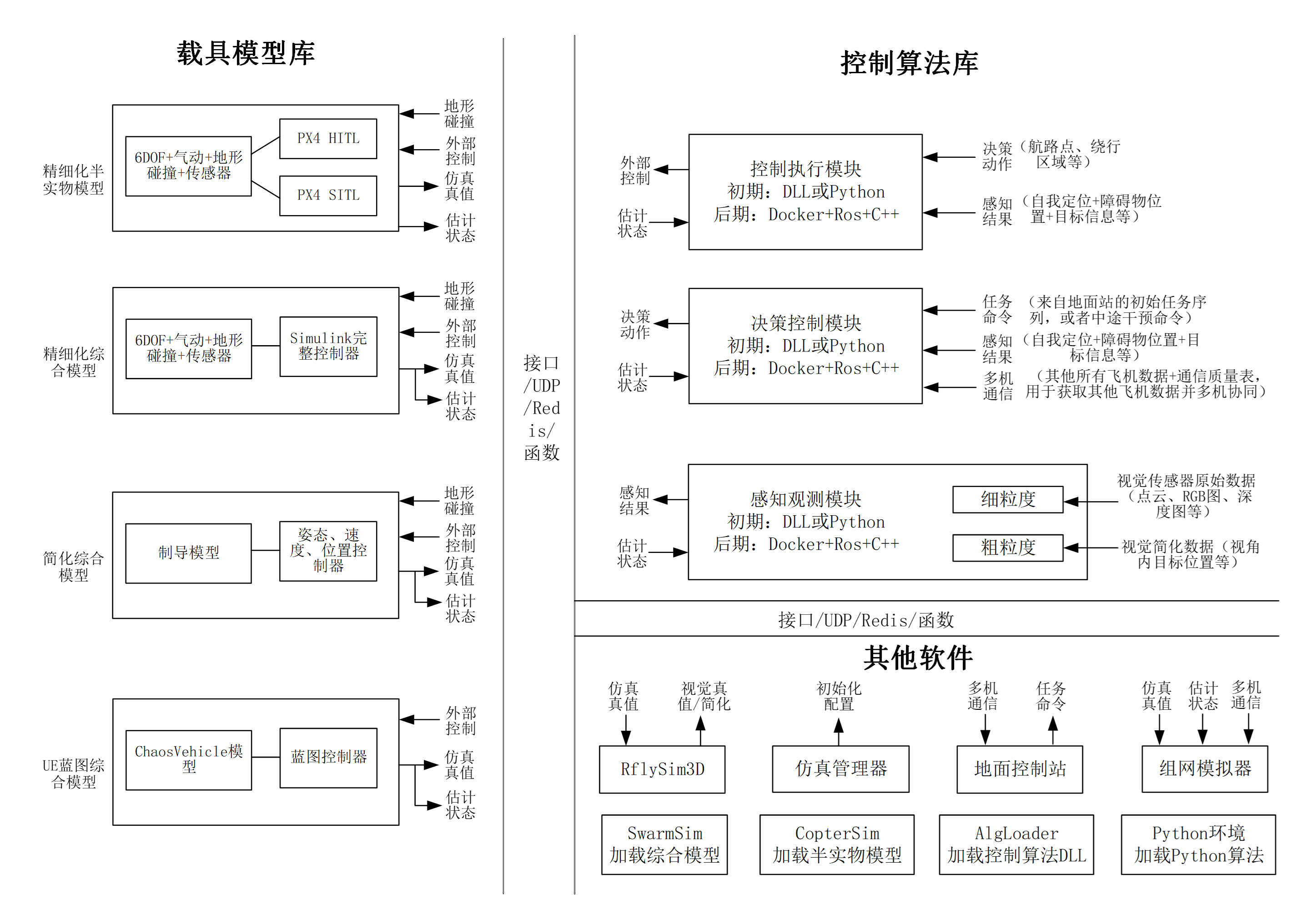
Utilizing a standardized modeling framework implemented in graphical modular simulation programming software such as Simulink, the final simulation system is obtained through code generation methods.
Models are categorized into four types, all supporting invocation as DLL by Python/Simulink/C++ to meet the requirements of large-scale swarms and AI training:
- High-fidelity 6-DoF model + flight control hardware-in-the-loop simulation
- High-fidelity 6-DoF model + integrated Simulink controller, generating a high-fidelity comprehensive model
- Simplified guidance model + integrated Simulink controller, generating a simplified comprehensive model
- UE physics engine + integrated Blueprints controller, generating a UE Blueprints comprehensive model (better response to terrain and collisions)
Models developed with this toolchain also support being exported as DLLs callable by Python and other programs, to accelerate AI control training—including decision-making and game-playing for deep reinforcement learning or large models.
Chapter 5: Low-Level Control and Filtering Estimation
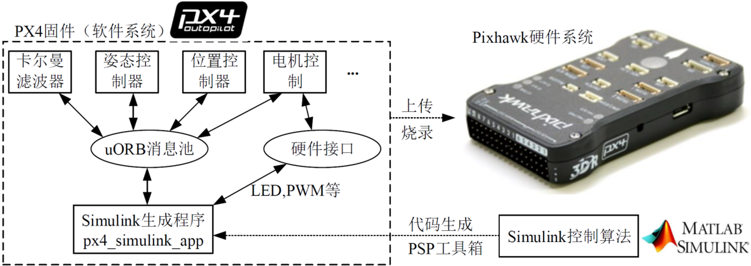
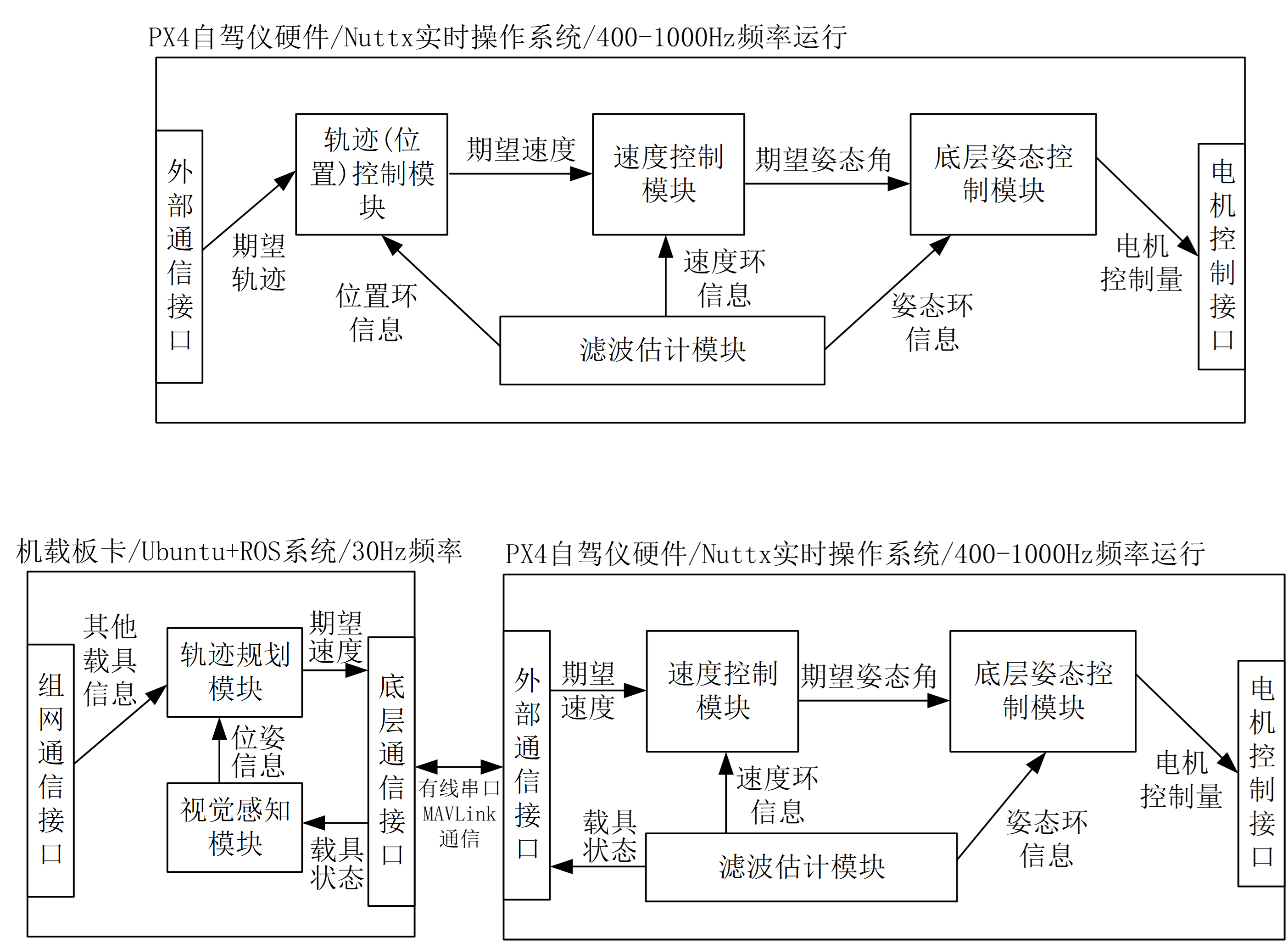
This chapter addresses model-based low-level flight control design: given control requirements, how to rapidly implement control algorithms on real aircraft? You only need to complete controller design in Simulink, then proceed through software-in-the-loop simulation, automatic code generation, hardware-in-the-loop simulation, indoor testing, and outdoor actual flight to quickly validate and deploy the algorithm. This significantly lowers the learning threshold for students in UAV control and enhances development efficiency for engineers.
Simulink controller development combined with automatic code generation eliminates the need for C/C++ low-level programming. By leveraging the uORB message pool, a ROS-like publish-subscribe mechanism is implemented, enabling more flexible algorithm embedding. For detailed introduction, see: Chapter 5 Filtering Estimation and Low-Level Control
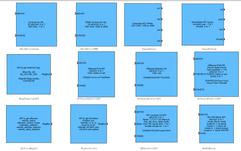
 New interface for low-level development (released with RflySim v3.03):
- Supports control input at any layer, including motor layer, force + torque layer, angular velocity layer, attitude angle loop, acceleration loop, velocity loop, position loop, and remote controller layer;
- Supports switching between official PX4 controllers and self-designed Simulink controllers during flight;
- Enables more convenient hardware-in-the-loop simulation and experimentation for various vehicle systems;
- Facilitates more convenient upper-layer information input (waypoints, trajectories, etc.).
Note: The current v3.02 version only supports motor-layer input and cannot switch back to the PX4 controller at any time, making algorithm development and experimentation more challenging. The new interface resolves this issue.
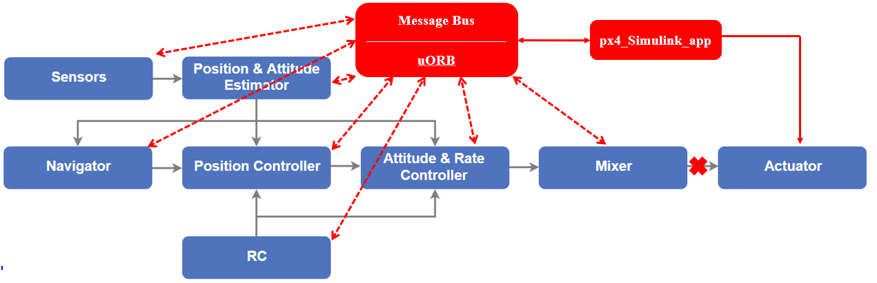
- PX4 adopts the uORB message publishing and subscribing mechanism, allowing any APP to retrieve and publish data from the uORB message pool.
- After generating code from Simulink and deploying it to Pixhawk, an APP named px4_Simulink_app is created, which can communicate with other APPs via the uORB message pool mechanism.
- System identification → accurate mathematical model → modern control theory (LQR, ADRC, MPC, MCC, etc.) → automatic code generation → direct deployment on flight controller V.S. repeatedly tuning PX4 native traditional PID to achieve optimal performance.
- Simulink only replaces the attitude loop, retains other loops, and conducts positioning and hovering tests under fan interference.
Conclusion: An accurate model + modern control theory + automatic code generation by RflySim enables rapid controller parameter calculation (no repeated parameter tuning required) and offers greater advantages in anti-interference performance (higher stability margin).
Recommended teaching aid: Feisi X150 UAV, 150mm wheelbase (180g weight), compact and safe, equipped with optical flow for stable indoor hovering, compatible with GPS for outdoor testing and motion capture for indoor experiments.
Combined with high-precision identification models and self-developed desktop test benches, it enables rapid development and verification of UAV algorithms.
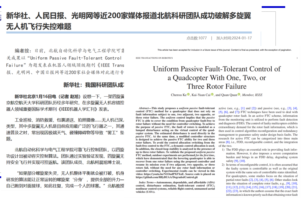
Based on modern fault-tolerant control theory, the RflySim toolchain enables controllable forced landing of a quadrotor when 1, 2, or 3 rotors fail. Accurate modeling → model-based control → automatic code generation → hardware-in-the-loop simulation → real aircraft testing facilitates rapid development of novel algorithms.
Chapter 6: External Control and Trajectory Planning
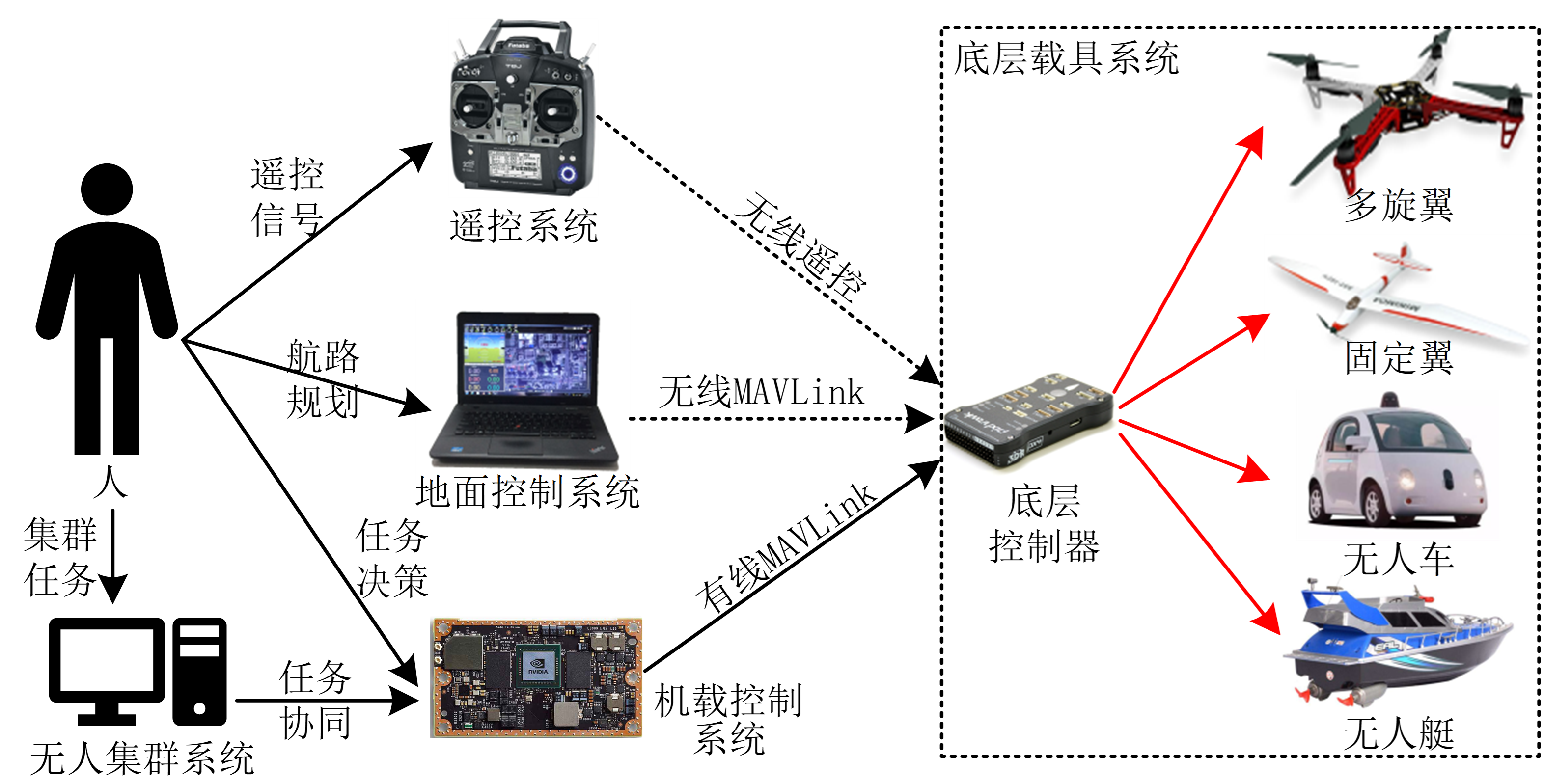
Modern flight control framework: The low-level flight controller retains only attitude or velocity loop control to ensure basic reliable flight capability. All other upper-level planning and control logic are deployed on the onboard computing board and transmitted to the flight controller via an external control interface. The low-level flight controller targets fixed airframe models and can be rapidly implemented using system identification + modern control methods + automatic code generation. Open-source flight controllers such as PX4 contain many redundant designs to accommodate UAVs of various sizes and types, making them unsuitable for UAV manufacturers or research institutions. For detailed introduction, see: Chapter 6 External Control and Trajectory Planning
Internal/external control is relative:
- The trajectory planning model for external control can also be placed inside the flight controller.
- Similarly, much logic of internal flight control can also be placed externally.
- Control tasks with higher maneuvering requirements can be placed inside the flight controller to run at a higher frequency.
- For example, high-maneuverability trajectory tracking, AI algorithm training for stunts such as window penetration and inverted flips, etc.
 Interface usage tutorial: Remote control operation, Mavlink communication, Pymavlink, Mavsdk, Mavros, ROS1/2. Algorithm development examples: Upper-level development with Simulink UAV algorithm library, trajectory generation, obstacle avoidance planning, AI training, etc.
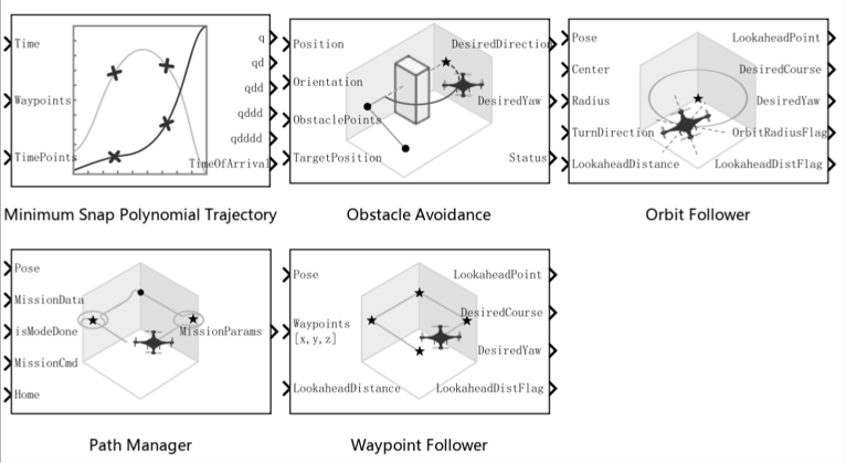
Low-Level Control Algorithms: It is recommended to leverage MATLAB/Simulink's rich control planning library and AI training library to rapidly develop and verify algorithms, and achieve swift algorithm deployment through automatic code generation.
Note: The RflySim toolchain also plans to be compatible with the domestic MWORKS platform in the future.
Chapter 7: Safety Assessment and Fault Diagnosis
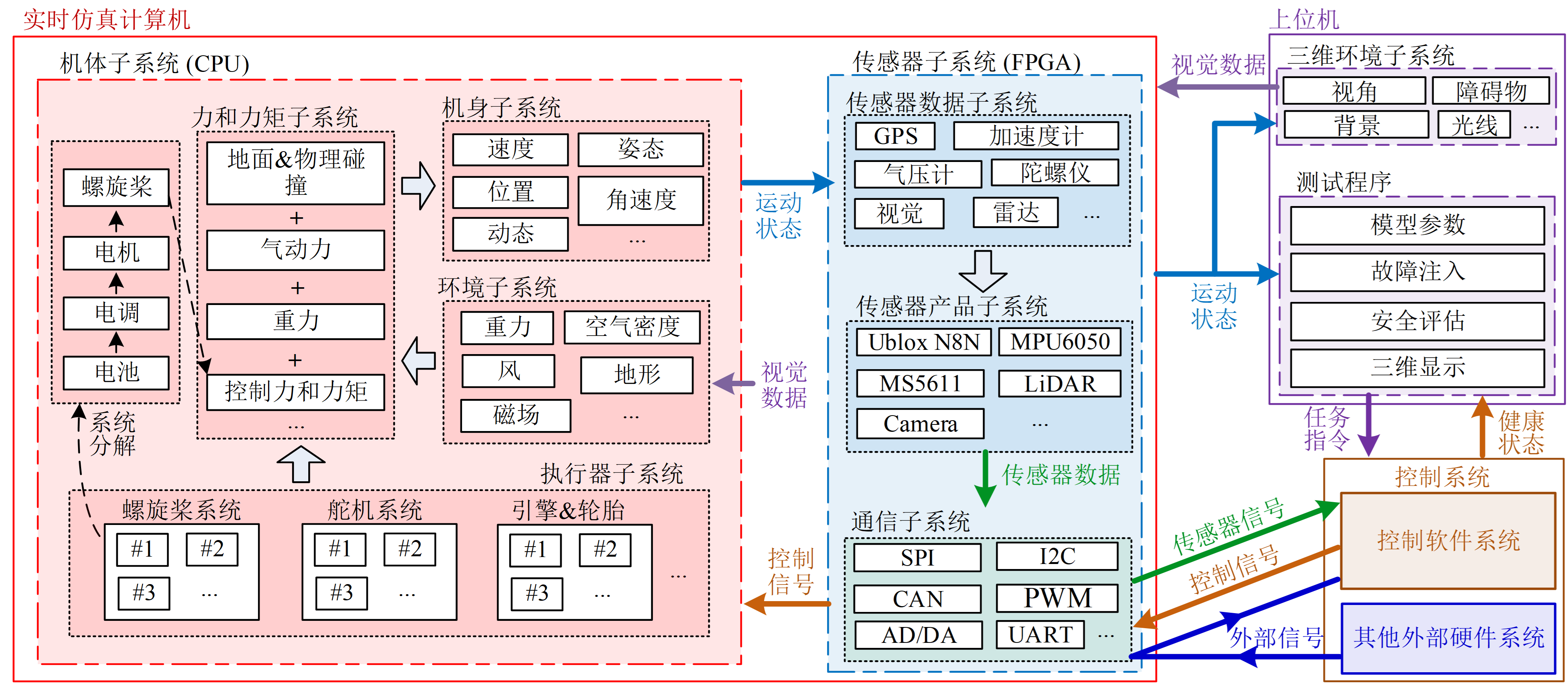
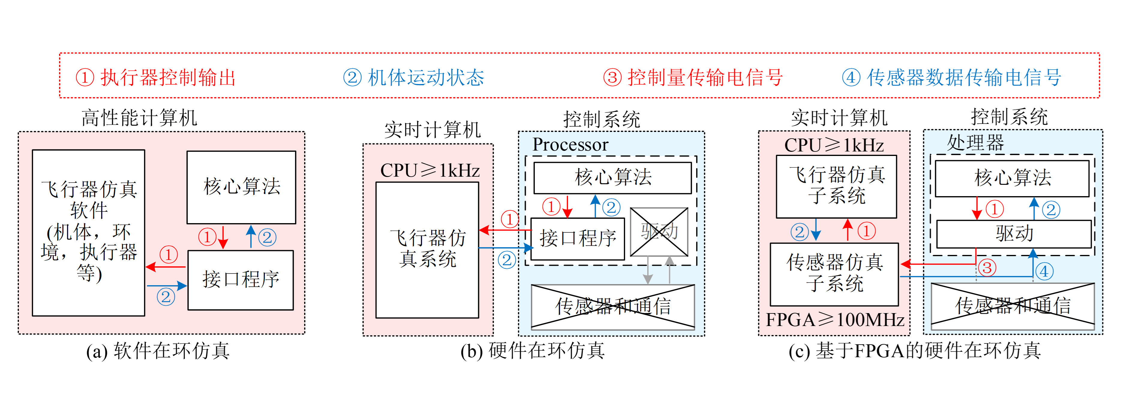
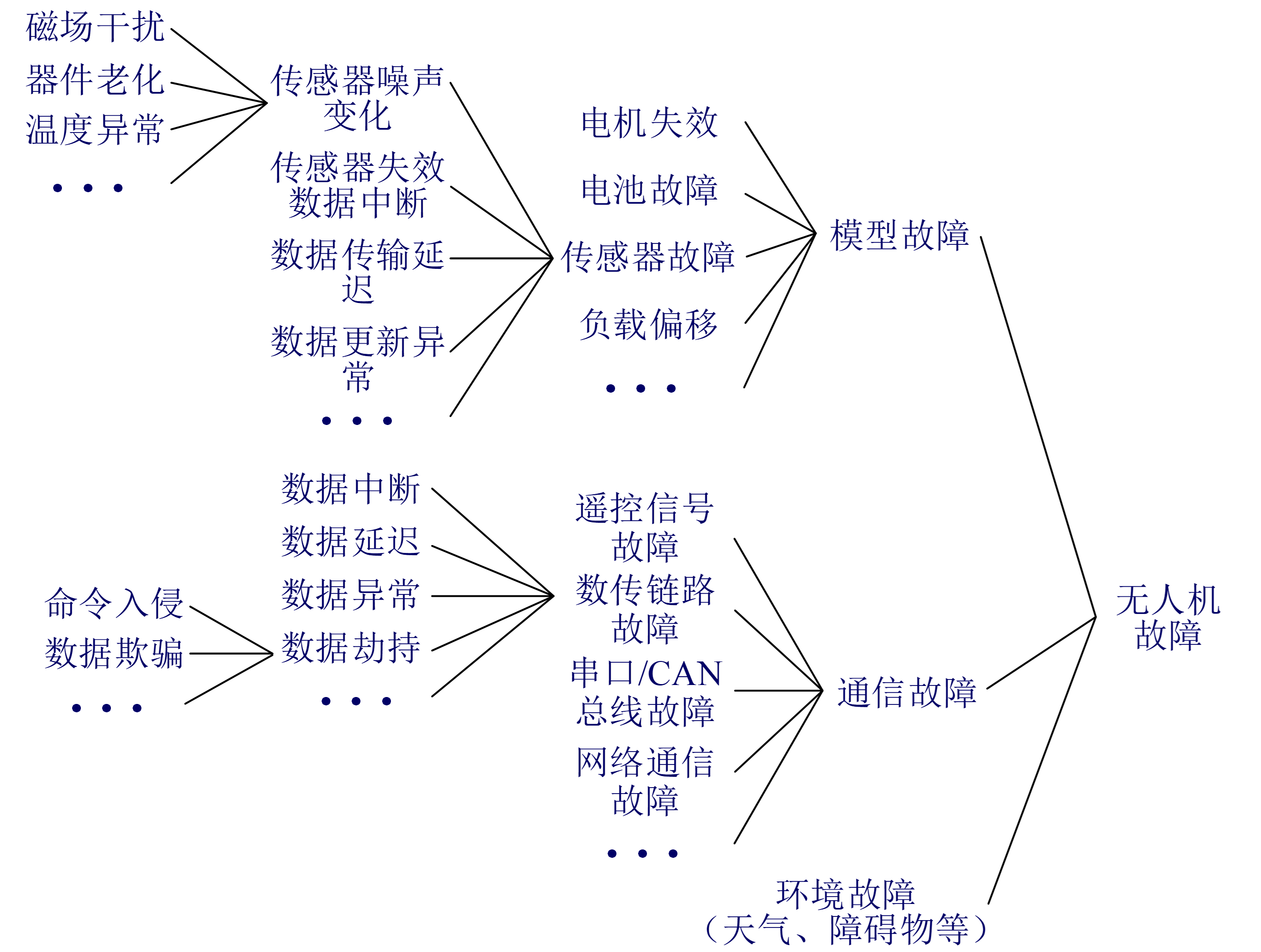
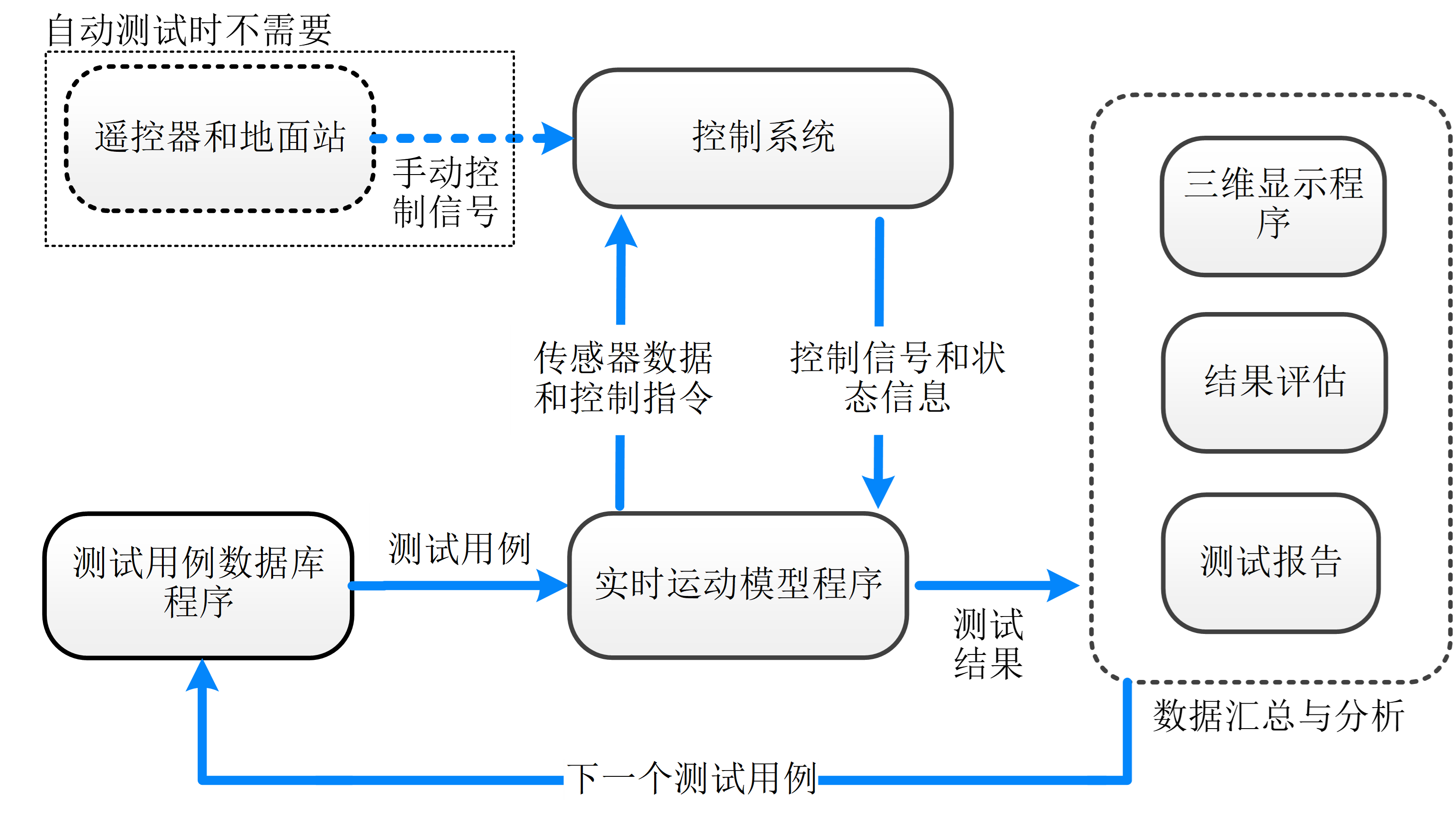
In addition to testing basic functions, safety and reliability testing under fault conditions is also critical for UAVs. This system categorizes faults into three types: model faults (related to the UAV's mathematical model), communication faults (related to data interaction and transmission), and environmental faults (related to 3D scenarios). For detailed introduction, see: Chapter 7 Health Management and Safety Assessment
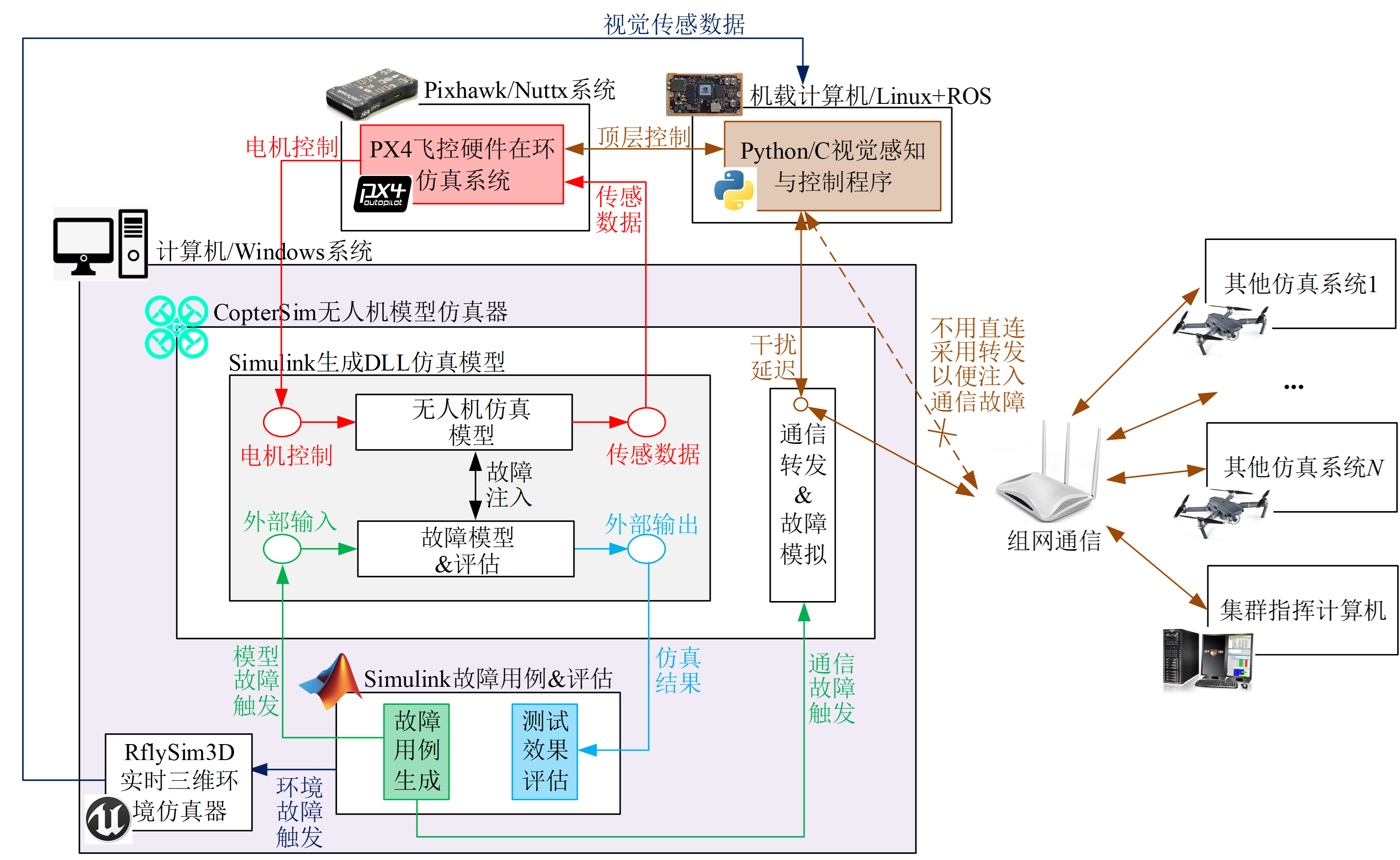
From kinematic and dynamic simulation → sensor data simulation → sensor chip simulation
From pure algorithm software testing → system-wide software and hardware testing
Chapter 8: Multi-Modal Perception and Intelligent Decision-Making
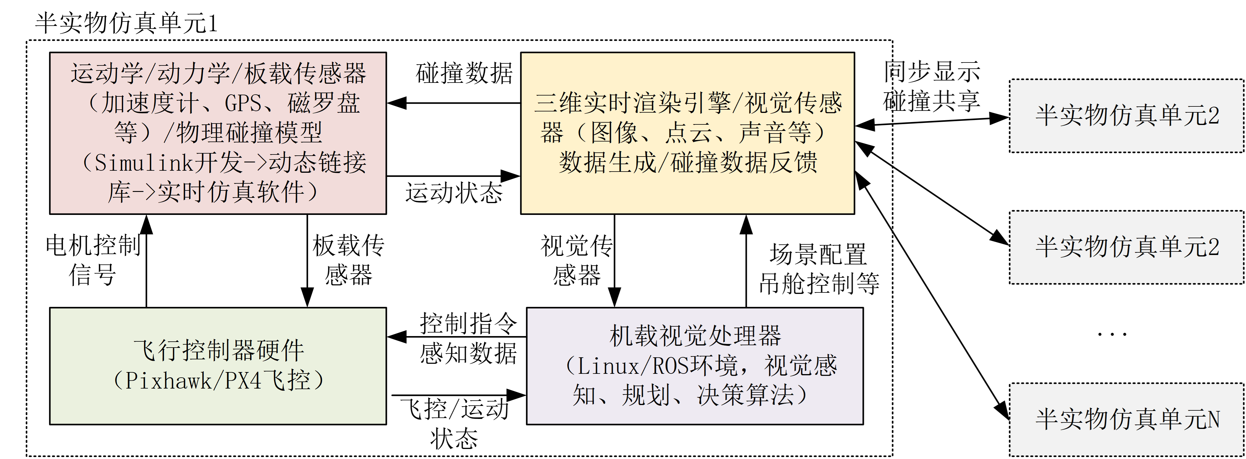
In this chapter, based on the distributed architecture, model outsourcing, semi-physical simulation, and multi-UAV synchronization features of the RflySim toolchain, users can perform developments such as distributed architecture implementation for independent visual hardware-in-the-loop verification of multiple UAVs, visual SLAM semi-physical simulation, and rapid migration of real-aircraft algorithms. For detailed introduction, see: Chapter 8 Multi-Modal Perception and Intelligent Decision-Making
Chapter 9: Multi-UAV Communication and Intelligent Networking
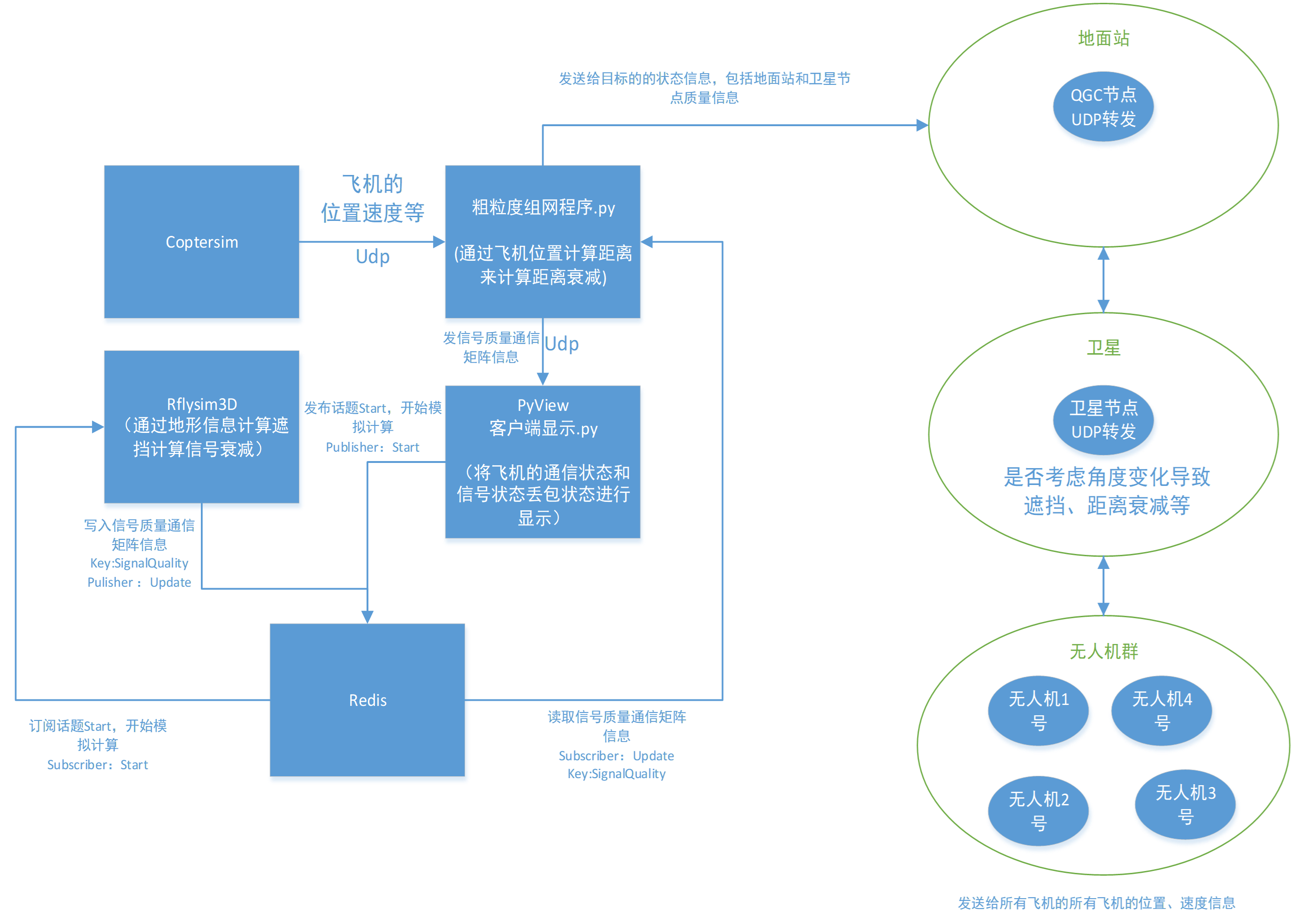
In this chapter, all UAV data is first sent to the network simulator, and then forwarded to subscribed UAVs based on actual conditions. Network simulation is divided into two granularities: coarse-grained simulation, which primarily simulates upper-layer characteristics such as delay and packet loss to emulate the final communication quality; and fine-grained networking simulation based on NS3, which supports the development and verification of lower-layer networking algorithms. For detailed introduction, see: Chapter 9 Multi-UAV Communication and Intelligent Networking
Chapter 10: Swarm Cooperation and Game Confrontation
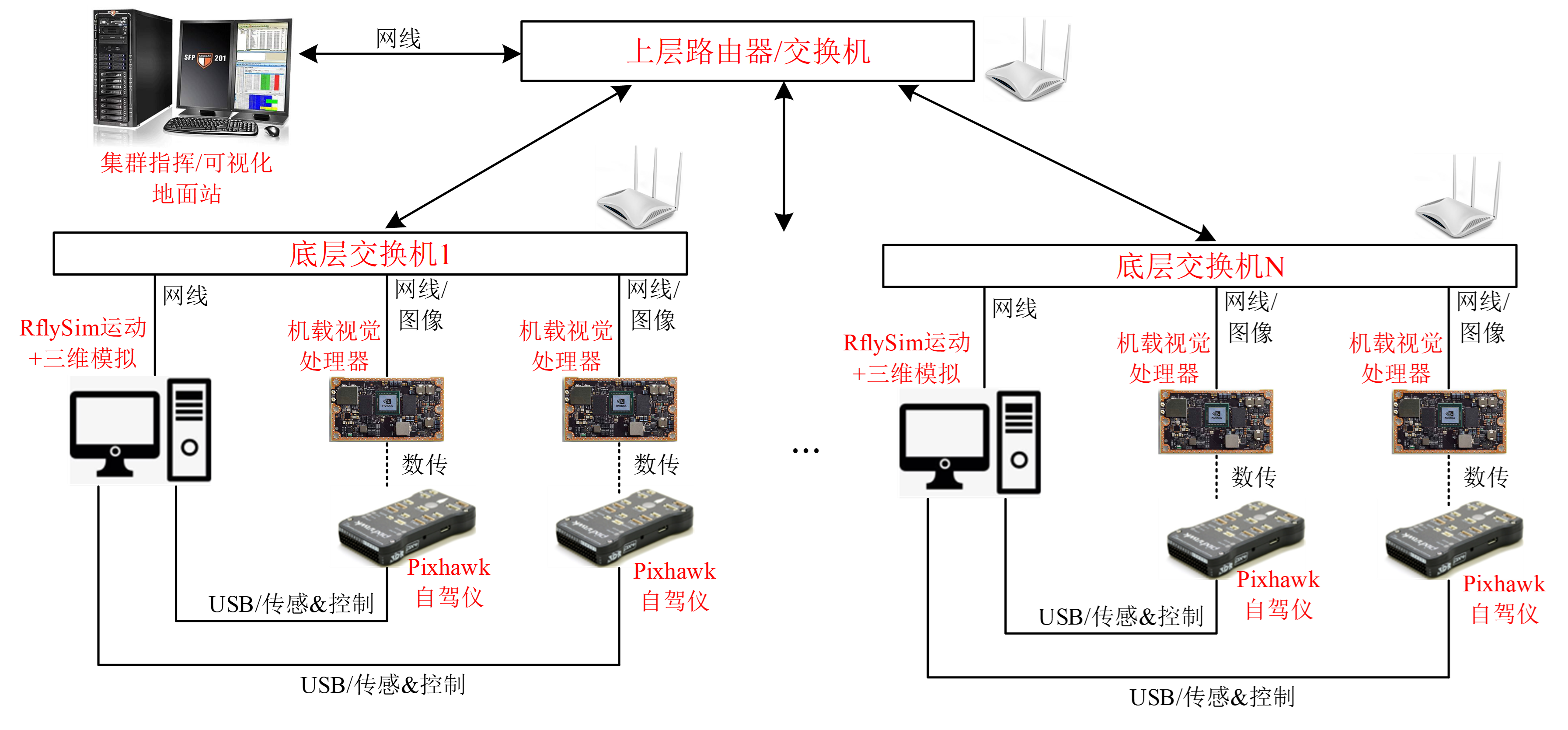
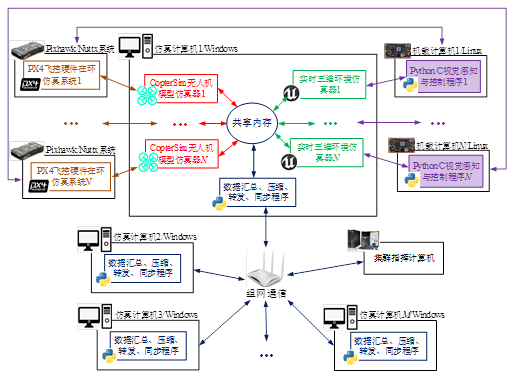
In this chapter, inter-program communication within a computer during swarm simulation adopts the shared memory method, operating directly on memory to achieve the lowest latency and highest speed. Each computer can run multiple hardware-in-the-loop/software-in-the-loop simulation systems to simulate multiple UAVs. Data transmitted and received by each computer is aggregated and compressed to ensure smooth intra-network communication. It uses on-demand communication and supports swarm simulation at the scale of 1,000 drones. For detailed introduction, see: Chapter 10 Swarm Cooperation and Game Confrontation
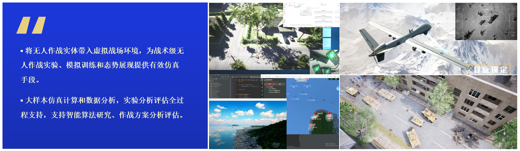
Introduction to RflySim Cloud
The RflySim Cloud intelligent algorithm cloud platform is developed by Feisi Lab under Zhuoyi Intelligence for cutting-edge research fields including large-scale swarm algorithm verification, unmanned platform game confrontation simulation, and artificial intelligence model training. It supports both public cloud and private cloud deployment, and is a comprehensive platform integrating large-scale high-fidelity model simulation with online development, debugging, and training for multiple types of intelligent algorithms.
The RflySim Cloud platform consists of modules including experiment management tools, scenario editing tools, system management tools, agent training tools, and model development tools. End users only need to provide their intelligent algorithms and connect them via the intelligent algorithm interface SDK; the algorithms can then directly utilize system modules such as system dynamics calculation and multi-agent training.
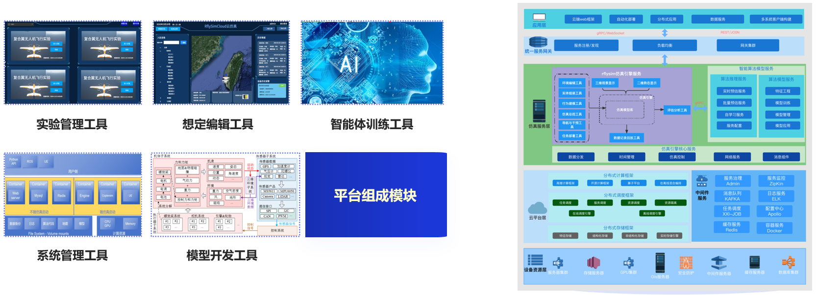
Cloud access, ultra-high computing power support, ultra-large-scale swarms, freeing local computing constraints.