ET10
Tifei ET10 
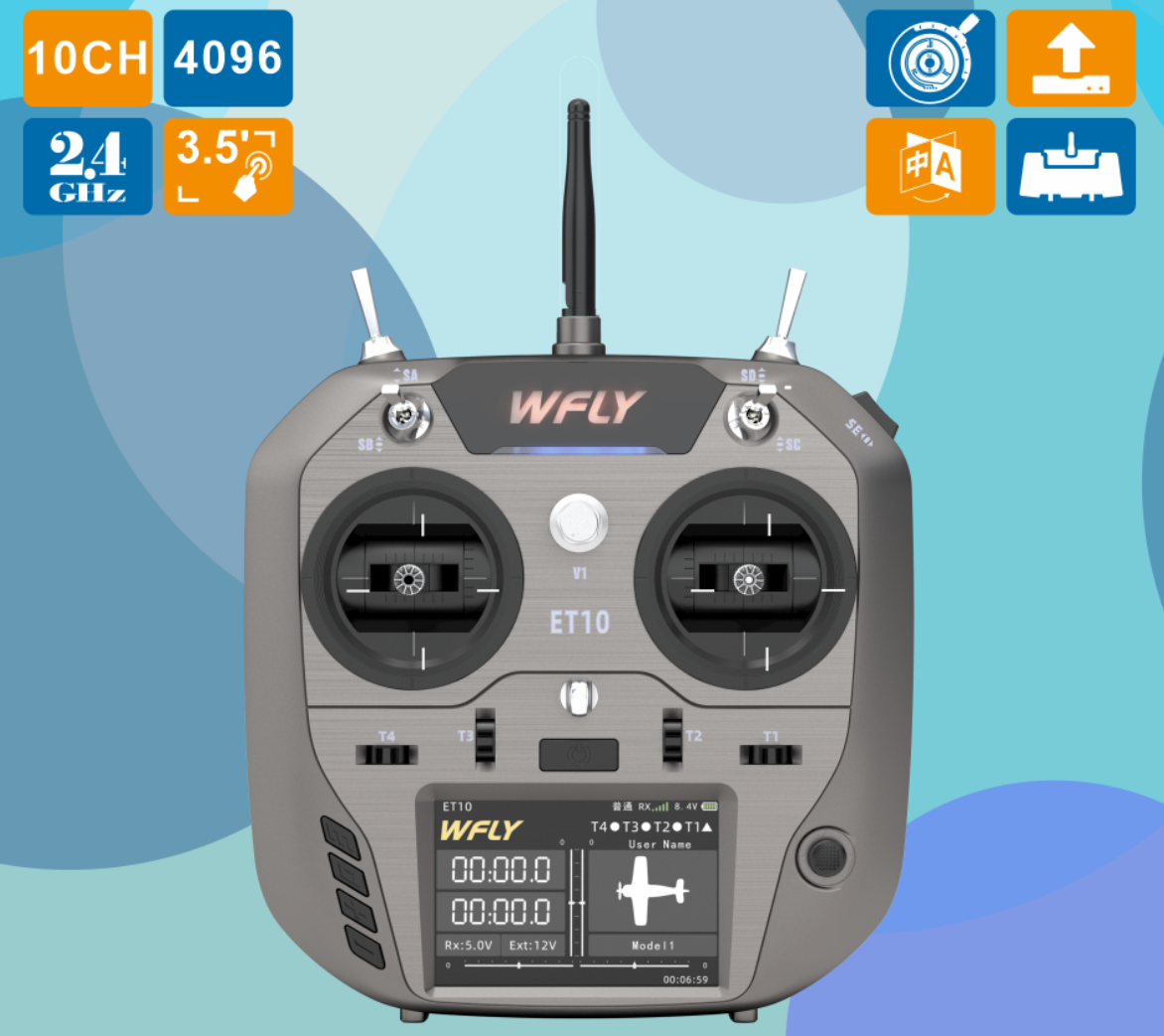
1. Product Introduction
The ET10 is an upgraded and enhanced version of the ET07, featuring full proportional 10 channels. It inherits the powerful expandability of the ET series and introduces several new features: an external high-frequency head NANO interface, compatibility with ELRS and TBS, Hall-effect joysticks, an enlarged battery compartment, a Type-C interface, and a liquid metal surface finish—delivering a completely refreshed user experience. For more information, please visit: http://www.wflysz.com/product/332.html
2. Product Appearance and Interface Overview
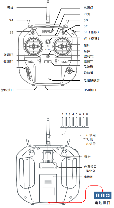
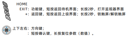
- Power switch: Press and hold for approximately 2 seconds to turn on or off
- T1~T4: Trim buttons (customizable functions)
- SA: Long-stroke two-position switch (customizable function)
- SB: Short-stroke three-position switch (customizable function)
- SC: Short-stroke three-position switch (customizable function)
- SD: Long-stroke two-position reset switch (customizable function)
- SE: Rocker-type three-position switch (customizable function)
- V1: Knob (customizable function)
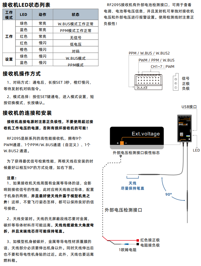
RF209S Receiver Notes
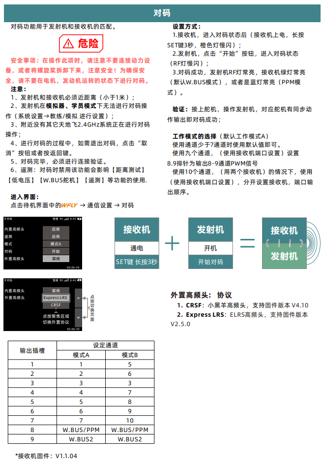
3. Transmitter Binding
4. Multirotor Simulation and Flight Configuration
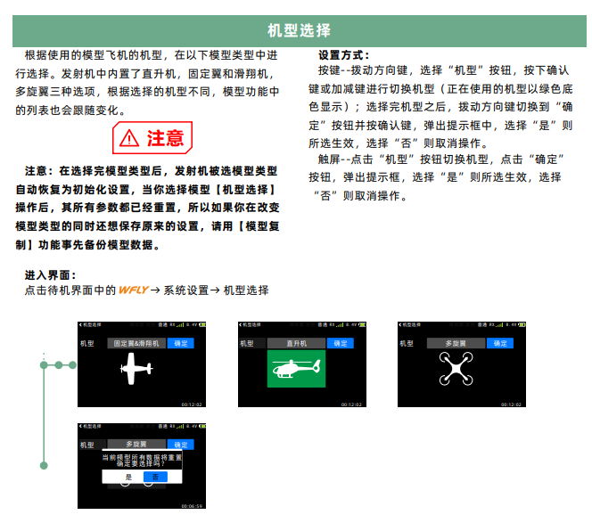
4.1. Aircraft Type Selection
Select the multirotor aircraft type as shown in the diagram below.
In the transmitter, roll, pitch, throttle, and yaw correspond to receiver channels CH1 to CH4, respectively. The left/right upper-side toggle switches correspond to channels CH5 and CH6, used to trigger flight mode switching.
The throttle stick (CH3 channel) corresponds to a PWM signal ranging from approximately 1100 to 1900 as it moves from the lowest to the highest position (variations may occur depending on channel or transmitter model, thus calibration is required); the roll (CH1 channel) and yaw (CH4 channel) sticks correspond to a PWM signal ranging from 1100 to 1900 as they move from left to right; the pitch (CH2 channel) stick corresponds to a PWM signal ranging from 1900 to 1100 as it moves from bottom to top; CH5/CH6 are three-position switches, with the top (farthest from the user), middle, and bottom (closest to the user) positions corresponding to PWM signals of 1100, 1500, and 1900, respectively.
Configuration and calibration procedure:
-
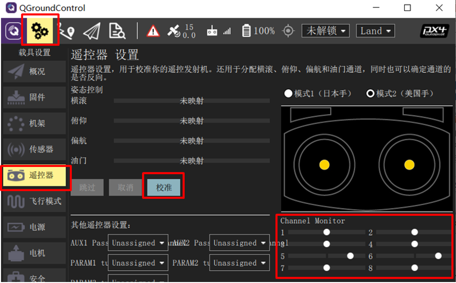
Connect the Pixhawk to the receiver correctly, then connect the Pixhawk to a computer via USB cable. Power on the transmitter and open the QGroundControl ground station software. Click the “Radio” tab.
-
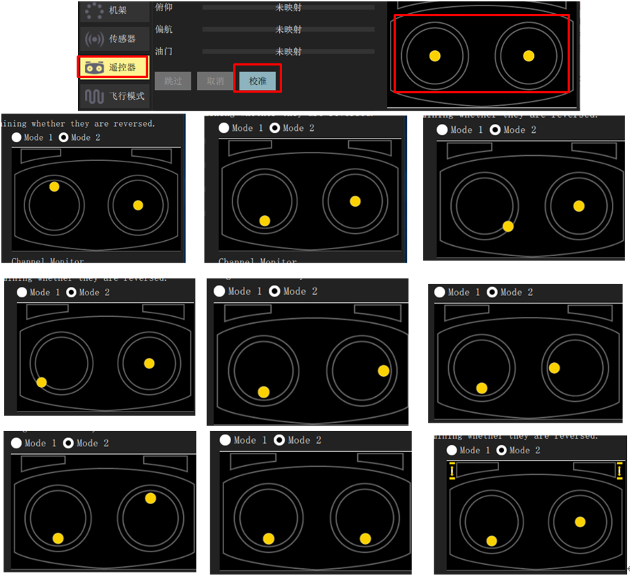
Move the transmitter’s CH1 to CH5 channels sequentially from left to right (or top to bottom, as shown in the upper-right diagram), and observe the white dots in the red box area on the right side of the ground station screen. If the white dots for channels 1, 2, 4, 5, and 6 move from left to right (PWM from 1100 to 1900), and dot for channel 3 moves from right to left, the transmitter configuration is correct. Otherwise, reconfigure the transmitter.
-
Click the “Calibrate” button in the lower-right image, and follow the on-screen prompts to calibrate the transmitter.
-
Click “Calibrate” → “Next” on the QGC ground station interface, then move the sticks to the positions shown in the diagram (as prompted in real time on the QGC screen) to complete the transmitter calibration.
4.2 Flight Mode Configuration
-
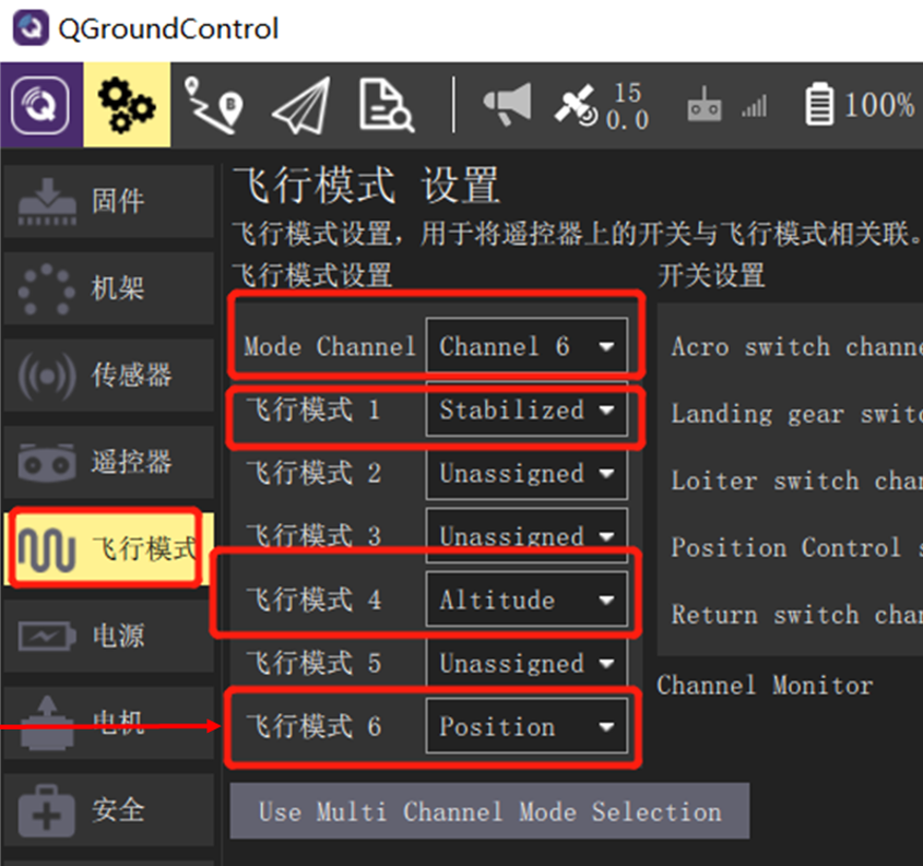
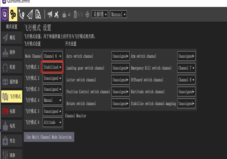
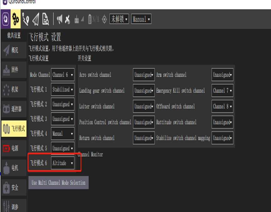
After completing the above transmitter calibration, click into the “Flight Modes” page on the ground station, and set “Mode Channel” to Channel 6 (the previously tested channel). Since CH6 is a three-position switch, the top, middle, and bottom positions correspond to the “Flight Mode” labels 1, 4, and 6, respectively.
-
Assign these three labels to “Stabilized” (Stabilized mode: attitude control only), “Altitude” (Altitude hold mode: attitude and altitude control), and “Position” (Position hold mode: attitude, altitude, and horizontal position control). In subsequent hardware-in-the-loop simulations, switching between these modes allows you to experience different control characteristics.
5. Mode Switching
5.1 Stabilized Mode (Multirotor)
In Stabilized mode, when the transmitter sticks are centered, the multirotor aircraft will stabilize itself. To manually move or fly the aircraft, displace the sticks from their centered positions. Under manual control, roll and pitch sticks control the aircraft’s angular orientation around each axis (attitude), the yaw stick controls the rotation rate about the vertical axis in the horizontal plane, and the throttle stick controls altitude or vertical speed.
Once the sticks are released, they return to the center deadzone. When roll and pitch sticks are centered, the multirotor will level out and cease motion, then hover in place or maintain altitude—provided the aircraft is properly balanced, throttle is appropriately set (see below), and no external forces (e.g., wind) are applied. The aircraft will drift downwind, and you must adjust throttle to maintain altitude.
5.2 Stabilized Mode (Fixed-Wing)
In Stabilized mode, centering the sticks causes the aircraft to enter straight and level flight, maintaining level attitude and resisting wind disturbances (but not heading or altitude).
If roll/pitch sticks are deflected, the aircraft climbs or descends based on pitch input and executes coordinated turns. Roll and pitch are angle-controlled (no loops or inverted flight possible).
If throttle is reduced to 0% (motor stops), the aircraft will glide. To execute a turn, the control input must be maintained throughout the maneuver, as releasing the roll stick will cause the aircraft to stop turning and automatically level its wings (same applies to pitch and yaw commands). Note: Stabilized mode makes it easy to maintain level flight simply by centering the sticks.
5.3 Altitude Hold Mode (Multirotor)
Altitude Hold mode is a relatively easy-to-fly manual mode. Roll and pitch sticks control lateral and forward/backward motion (relative to the aircraft’s “nose”), yaw stick controls rotation rate in the horizontal plane, and throttle controls vertical ascent/descent rate.
When sticks are released or centered, the aircraft levels out and maintains its current altitude. If moving horizontally, the aircraft continues moving until momentum is dissipated by aerodynamic drag. In wind, the aircraft will drift downwind. Note: For beginners, Altitude Hold is the safest manual mode without GPS—similar to Stabilized mode, but with altitude locking upon stick release.
Altitude Hold mode makes it easier for the operator to control the aircraft’s altitude, especially when reaching and maintaining a fixed altitude. This mode does not attempt to resist wind disturbances to maintain heading.
Climb/descent rate is controlled via the pitch/elevator stick. Once the stick is centered, the autopilot locks the current altitude and maintains it regardless