RflySim Model – Simulation Model–Related Module Library
The RflySim Model library provides a complete set of drone simulation modeling tools, including a six-degree-of-freedom (6-DOF) dynamics model, motor model, force model, ground model, and various communication interface modules, supporting full-scenario simulations from single-drone to multi-drone systems.
Module List
Dynamics Models
| Module | Function Description |
|---|---|
| 6DOF | Six-degree-of-freedom rigid-body dynamics model, computing the drone’s position, velocity, attitude, angular velocity, and other motion states |
| Copter Force Model | Multi-rotor aerodynamic force model, calculating thrust, torque, and drag generated by rotors |
| Copter Motor Model | Multi-rotor motor model, simulating motor dynamic response and speed characteristics |
| Ground Model | Ground interaction model, simulating contact forces and friction between landing gear and ground |
Communication Interfaces
| Module | Function Description |
|---|---|
| UDP 20100 PX4SIL Recv | PX4SIL UDP data reception interface, receives PX4 simulation data on port 20100 |
| UDP 30100 TrueSim Recv | TrueSim UDP data reception interface, receives high-precision simulation data on port 30100 |
| UDP 40100 RflyPX4 Recv | RflyPX4 UDP data reception interface, receives RflySim PX4 data on port 40100 |
| PX4SIL IntFloat Send | PX4SIL integer/float data transmission interface, sends integer and floating-point control data to PX4 |
| PX4 Fault Params Send | PX4 fault parameter transmission interface, injects fault parameters into the flight controller |
Output Interfaces
| Module | Function Description |
|---|---|
| 3D Output | 3D visualization output interface, sends position and attitude data to RflySim3D |
| Sensor Output | Sensor data output interface, outputs simulated data for various sensors |
Usage Scenarios
Single-Drone Simulation
- Dynamics Modeling: Use the 6DOF module to build the drone’s rigid-body dynamics model
- Motor Modeling: Combine the Copter Motor Model and Copter Force Model to construct a complete multi-rotor power system
- Ground Interaction: Use the Ground Model to simulate landing gear–ground contact forces
Hardware-in-the-Loop (HIL) Simulation
- PX4SIL Interface: Use UDP 20100/30100/40100 reception modules to communicate with CopterSim
- Control Data Transmission: Use PX4SIL IntFloat Send to transmit control commands to the flight controller
- 3D Visualization: Use 3D Output to send simulation data to RflySim3D for display
Fault Injection Simulation
- Fault Parameter Injection: Use PX4 Fault Params Send to inject various fault parameters into the flight controller
- Sensor Faults: Simulate sensor fault data via the Sensor Output module
Usage Notes
Dynamics Modeling
- Parameter Accuracy: Parameters such as mass and moments of inertia in the 6DOF module must match the actual drone; otherwise, simulation results will be distorted
- Coordinate System Convention: The modules use the NED (North-East-Down) coordinate system and body-fixed frame; input/output data must conform to this convention
- Initial Conditions: Set reasonable initial position, velocity, and attitude to avoid simulation divergence caused by conflicting initial states
- Numerical Stability: The simulation time step should not be too large; a fixed step size of ≤1 ms is recommended to ensure numerical integration stability
Communication Interfaces
- Port Configuration: UDP reception/transmission module port numbers must match CopterSim configuration to prevent communication failures
- Network Settings: Ensure the firewall allows UDP communication on the corresponding ports, especially in multi-drone scenarios
- Data Synchronization: The sampling time of communication modules must match the Simulink model time step to avoid data misalignment
- Timeout Handling: Reception modules must implement appropriate timeout mechanisms to prevent simulation hangs due to communication interruptions
Fault Injection
- Parameter Range: Fault parameters must be within reasonable bounds; excessively large or small values may cause simulation crashes
- Fault Timing: Choose appropriate fault injection timing to avoid injecting severe faults during critical control phases
- Recovery Mechanisms: Design fault recovery logic to test system fault tolerance and self-recovery capabilities
- Safety Boundaries: Define simulation safety boundaries and automatically terminate the simulation when states exceed safe limits
Unified Modeling Interface and Model Templates
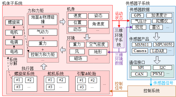
A comprehensive RflySim model typically consists of an input interface, dynamics/actuator/environment modules, sensor output modules, and a 3D display output module. Interface naming is consistent across multi-rotor, fixed-wing, vehicle/vessel, VTOL, helicopter, and custom models, facilitating model replacement without modifying the upper-level control chain.
Unified Input Interface
| Interface | Type | Purpose |
|---|---|---|
inPWMs |
PWM/normalized control values | Actuator input from PX4, remote control, or external controller |
inCopterData |
Vehicle state structure | For arming status, mode, control state, and simulation synchronization |
inFloatsCollision / inCollision20d |
Float array | Collision, contact, terrain, and other external states |
inSILInts |
8-dimensional int | Software-in-the-loop integer input |
inSILFloats |
20-dimensional float | Software-in-the-loop float input |
inFromUE |
UE/RflySim3D input | Interactive information returned from 3D scenes or sensors |
TerrainIn15d |
15-dimensional terrain input | Terrain height, normal, contact point, and other ground model information |
inCtrlExt / inDoubCtrls |
External control input | Custom controller or host computer input |
inSIL28d |
28-dimensional SIL input | Comprehensive SIL model input interface |
inPWMs is a 16-dimensional actuator control input, with values normalized to -1 to 1. It corresponds to the MAVLink mavlink_hil_actuator_controls_t.controls returned by the flight controller, and its real-time changes can be viewed in QGroundControl's MAVLink Analyze tool. In software-in-the-loop mode, PX4 SITL sends motor control commands to the motion model via TCP 4561++ series ports; in hardware-in-the-loop mode, the flight controller sends similar MAVLink commands to the model via serial port.
Key Dimensions of inCopterData
inCopterData is a 32-dimensional double data array. Dimensions 1-8 store PX4/CopterSim states, dimensions 9-24 store RC channels, and dimensions 25-32 listen for the rfly_px4 uORB message.
| Dimension | Meaning |
|---|---|
1 |
PX4 arming flag |
2 |
Total number of received RC channels; 0 when no RC channels are available |
3 |
Simulation mode flag: 0=HITL, 1=SITL, 2=SimNoPX4 |
4 |
3D fixed flag in CopterSim |
5 |
PX4 VTOL_STATE flag |
6 |
PX4 LANDED_STATE flag |
9-24 |
ch1-ch16 RC channel signals |
25-32 |
rfly_px4 uORB extended message |
External Input Structure
inSILInts and inSILFloats are input via the 30100++2 series ports and are important entry points for comprehensive models.
struct PX4SILIntFloat {
    int checksum;          // 1234567897
    int CopterID;
    int inSILInts[8];
    float inSILFLoats[20];
};
inFromUE comes from RflySim3D/RflySimUE5 and can be used for ground interaction, collision engine, and blueprint data return.
inCtrlExt1-inCtrlExt5 require a 28-dimensional float input, while inDoubCtrls requires a 28-dimensional double input, both received via the 30100++2 series ports. The former is commonly used for fault injection, parameter modification, and small-scale extended control, while the latter is suitable for comprehensive models requiring double-precision external input.
inDoubCtrls is a 28-dimensional double input, suitable for large-scenario comprehensive model simulation:
TerrainIn15d Dimensions
| Dimension | Meaning |
|---|---|
1 |
Terrain height, positive downward in NED coordinate system |
2 |
haslop, whether there is a slope |
3 |
Pitch, in rad |
4 |
Yaw, in rad |
5 |
hasFric, whether there is friction |
6 |
FrictionFactor, friction coefficient |
7 |
isMoveObj, whether it is a moving object |
8 |
objVx, X-direction velocity of the moving object |
9 |
objVy, Y-direction velocity of the moving object |
10 |
objYaw, yaw angle of the moving object |
11-15 |
Reserved |
Unified Output Interface
| Interface | Type | Purpose |
|---|---|---|
HILSensor30d |
30-dimensional double | HIL sensor output for IMU, barometer, magnetometer, etc. |
HILGPS30d / MavHILGPS |
GPS data | GPS position, velocity, timestamp, etc. output |
ExtToPX4 |
External to PX4 data | Extended control or sensor data sent to PX4 |
VehileInfo60d |
60-dimensional double | Vehicle truth state, attitude, velocity, and auxiliary information |
outCopterData |
CopterSim output structure | DLL model output to CopterSim or external logs |
ExtToUE4 |
UE output | Vehicle pose, display, and object information sent to RflySim3D/UE |
HIL Sensor Output
HILSensor30d corresponds to the MAVLink mavlink_hil_sensor_t, containing three-axis acceleration, three-axis angular velocity, three-axis magnetic field, absolute pressure, differential pressure, pressure altitude, temperature, and a field update bitmask. In software-in-the-loop mode, it is sent to PX4 SITL via TCP 4561++ series ports; in hardware-in-the-loop mode, it is sent to the flight controller via serial port.
| Field | Meaning | Unit or Notes |
|---|---|---|
time_usec |
Timestamp | Microseconds, can be synchronized to UNIX time or system boot time |
xacc / yacc / zacc |
Three-axis acceleration | m/s^2 |
xgyro / ygyro / zgyro |
Three-axis angular velocity | rad/s |
xmag / ymag / zmag |
Three-axis magnetic field strength | Gauss |
abs_pressure |
Absolute pressure | Millibar |
diff_pressure |
Differential pressure or airspeed-related pressure | Millibar |
pressure_alt |
Pressure altitude | Meters |
temperature |
Temperature | Degrees Celsius |
fields_updated |
Update field bitmask | Bit 0 corresponds to xacc, bit 12 corresponds to temperature, bit 31 indicates a complete state reset in simulation |
HIL GPS Output
HILGPS30d / MavHILGPS corresponds to the MAVLink mavlink_hil_gps_t, containing latitude, longitude, altitude, horizontal/vertical accuracy, ground speed, NED velocity, ground course, fix type, and number of visible satellites.
| Field | Description | Unit or Remarks |
|---|---|---|
time_usec |
Timestamp | Microseconds |
lat / lon |
WGS84 latitude, longitude | 1e-7 deg |
alt |
Altitude above sea level | Millimeters, positive upward |
eph / epv |
Horizontal/vertical positioning accuracy | Centimeters, 65535 when unknown |
vel |
GPS ground speed | cm/s, 65535 when unknown |
vn / ve / vd |
NED north, east, down velocity | cm/s |
cog |
Course over ground | 0.01 deg, 65535 when unknown |
fix_type |
Fix type | 0-1 no fix, 2 2D fix, 3 3D fix |
satellites_visible |
Number of visible satellites | 255 when unknown |
Ground Truth and Log Output
VehileInfo60d contains vehicle ID, type, simulation time, NED velocity, NED position, Euler angles, quaternion, motor RPM, body-frame acceleration, body-frame angular velocity, and GPS position. outCopterData is a 32-dimensional double custom log output that can be written to a local CopterSim CSV log or output to external programs via the 30101 series ports.
| Field | Description | Dimension |
|---|---|---|
copterID |
Drone ID | 1 |
vehicleType |
Vehicle type | 1 |
runnedTime |
Current simulation timestamp | 1 |
VelE |
NED coordinate velocity, north, east, down | 3 |
PosE |
NED coordinate position, north, east, down | 3 |
AngEuler |
Roll, pitch, yaw Euler angles | 3 |
AngQuatern |
Attitude quaternion | 4 |
MotorRPMS |
Motor RPM for motors 1-8 | 8 |
AccB |
Body-frame three-axis acceleration | 3 |
RateB |
Body-frame three-axis angular velocity | 3 |
PosGPS |
Longitude, latitude, and altitude | 3 |
Before outCopterData is output to the local log, a CopterSim*.csv file corresponding to the aircraft number must be created under C:\PX4PSP\CopterSim, where * is the aircraft ID.
Fixed-Wing Model Template
The core of the fixed-wing model is to convert control surfaces, motors, aerodynamic states, and environmental disturbances into body-frame forces/torques, which are then integrated by the 6DOF module to obtain vehicle motion.
| Module | Description |
|---|---|
ControlChannelMappingModel |
Maps flight controller channels to control surfaces and throttle |
Actuator Model |
Servo dynamics, saturation, dead zone, and rate limits |
Motor Model |
Propeller thrust, reaction torque, and RPM dynamics |
GroundSupportModel |
Ground support, taxiing, touchdown, and collision handling |
Weather Model |
Wind speed, direction, gusts, and air density |
Aerodynamic Forces and Moments |
Lift, drag, side force, and three-axis aerodynamic moments |
6DOF |
Rigid-body six-degree-of-freedom integration |
3DOutput / SensorOutput |
3D visualization output and flight controller sensor output |
Aerodynamic force calculation typically proceeds sequentially through airspeed, angle of attack, sideslip angle, aerodynamic coefficients, dynamic pressure, control surface deflection, and moment arms, finally combining with engine thrust, gravity, ground forces, and disturbance forces as input to 6DOF.
The typical submodule implementation order for the fixed-wing model is: read model parameters, map inPWMs control surface/throttle channels, calculate servo dynamic response, compute propulsion system thrust based on airspeed, calculate air density and aerodynamic states, then convert forces/torques from the airflow coordinate system to the body frame and input them into 6DOF.
Minimal Model Template
The minimal model template is suitable for quickly building new vehicle dynamics. It retains the minimum input/output required for interfacing with RflySim/PX4 and splits actuators, forces/torques, ground, and sensor modules into replaceable subsystems.
| Module | Function |
|---|---|
Motor Model |
Converts control inputs to actuator outputs |
Force and Moment Model |
Calculates total forces/torques based on actuators, gravity, environment, and payload |
GroundSupport |
Ground altitude, touchdown detection, and support reaction forces |
6DOF |
Attitude, velocity, and position integration |
SensorOutput |
Generates HIL sensor data |
GPS Model |
Generates GPS position, velocity, and timestamp |
Environment Model |
Environmental inputs such as wind, air density, and disturbances |
In the minimal system template, MotorNonlinearDynamic1~8 each describe the nonlinear dynamic process of each motor. The static process converts PWM/throttle to desired RPM, while the dynamic process approaches the desired RPM using the motor response time constant; the Force and Moment Model then calculates total thrust and three-axis torque based on motor layout, rotation direction, and moment arms.
Gazebo Model Interface Modules
| Module | Description |
|---|---|
ESC_ALL / ESC |
ESC response, saturation, and motor command conversion |
MOTOR_ALL / MOTOR |
Motor RPM, thrust, and reaction torque model |
LIFTDRAG_ALL / LIFTDRAG |
Lift and drag aerodynamic model |
When converting Gazebo models, coordinate systems, units, rotation directions, channel order, and torque positive directions must be unified.
Simulink/DLL and ROS Forwarding
Integrated models can exchange data with ROS systems via Simulink or DLL. Key data structures include:
| Data Structure | Size | Direction | Description |
|---|---|---|---|
SOut2Simulator |
168 bytes | Simulink/DLL to simulator | Integrated model output state, sensor, or control data |
SILIntFloat |
120 bytes | Simulator/ROS to Simulink/DLL | 8 integers and 20 floating-point inputs |
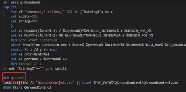
During runtime, PX4, CopterSim, RflySim3D, and the integrated model are typically started first. The integrated model then listens on the 20100/30100/40100 series ports, forwards state or sensor results to ROS topics, and receives control or mission results written back by ROS nodes.
Related Resources
- PX4 Official Documentation – Simulation
- RflySim Development Documentation – CopterSim
- MATLAB Documentation – 6-DOF Equations of Motion
Note: This document serves as the index for the RflySim Model library. For detailed usage instructions of each module, please refer to its dedicated documentation page.