6DOF Module Documentation
Toolbox: RflySim Model
Introduction
One-sentence description: This module integrates a quaternion-based rigid-body 6-DOF motion model and a simplified environmental model to compute the position, attitude, velocity, and other motion states of an unmanned vehicle during flight, providing standardized bus output.
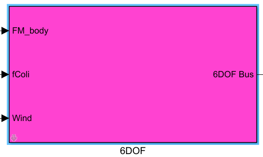
This module serves as the core foundational component for unmanned system dynamics simulation within the RflySim Model toolchain, primarily targeting dynamic simulation development scenarios for various fixed-wing, multi-rotor, and other unmanned vehicles. It accepts inputs—including net force and moment vectors (from force and moment calculation modules), collision and friction-induced force and moment vectors (from collision modules), and environmental wind velocity (from wind disturbance modules)—and, in conjunction with user-configured vehicle parameters such as mass, inertia tensor, and initial motion states, solves the rigid-body 6-DOF equations of motion using the quaternion method. Simultaneously, it converts station-centered NED coordinates to geodetic LLA (Latitude–Longitude–Altitude) GPS coordinates via a simplified environmental model and computes local gravitational acceleration based on the WGS 84 reference ellipsoid. Finally, all motion states and environmental parameters are packaged into a standard Simulink Bus output.
Within the RflySim simulation toolchain, the vehicle pose and motion states computed by this module are further transmitted to CopterSim to enable hardware-in-the-loop (HIL) simulation with the PX4 flight controller, and simultaneously sent to RflySim3D for 3D visualization of the flight process, supporting the entire development workflow from dynamics modeling to closed-loop simulation and visualization-based verification.
Port Descriptions
Input Ports
| Port Name | Data Type | Dimension | Description |
|---|---|---|---|
FM_body |
double |
1×6 |
Concatenated vector of net force and moment acting on the vehicle in the body-fixed frame, output by the force and moment calculation module |
fColi |
double |
1×6 |
Concatenated vector of force and moment due to collision and friction in the body-fixed frame, output by the collision and ground interaction modules; input zero vector if no corresponding module is present |
Wind |
double |
1×3 |
Wind velocity vector in the station-centered frame (typically NED), output by the wind disturbance module; input zero vector if no corresponding module is present |
Output Ports
| Port Name | Data Type | Dimension | Description |
|---|---|---|---|
6DOF Bus |
Bus |
- | Simulink Bus object encapsulating all outputs from both the simplified environmental model and the rigid-body 6-DOF model, including position, velocity, attitude, angular velocity, GPS coordinates, and all other motion state information |
Parameter Configuration
The following parameters can be configured in the Mask dialog box opened by double-clicking the module:
| Parameter Name | Type | Default Value | Valid Values/Range | Description |
|---|---|---|---|---|
Init_PosE |
double |
[0 0 0] |
Any 3D vector | Initial vehicle position in the station-centered frame (typically NED), in meters |
Init_VelB |
double |
[0 0 0] |
Any 3D vector | Initial velocity vector of the vehicle in the body-fixed frame (x, y, z), in m/s |
Init_AngEuler |
double |
[0 0 0] |
Any 3D vector | Initial Euler attitude angles of the vehicle in the body-fixed frame, in radians (rad) |
Init_RateB |
double |
[0 0 0] |
Any 3D vector | Initial angular velocity vector of the vehicle about the body-fixed x, y, z axes, in rad/s |
Param_uavMass |
double |
1 |
>0 |
Total mass of the unmanned vehicle, in kg |
Param_uavJ |
double |
diag([0.01, 0.01, 0.02]) |
3×3 diagonal matrix with positive diagonal entries | Vehicle inertia tensor; diagonal entries represent moments of inertia about the principal body-fixed x, y, z axes, in kg·m² |
Param_GPSLatLong |
double |
[30.533800, 114.358200] |
2D vector; latitude range (-90, 90), longitude range (-180, 180) |
Latitude and longitude of the map GPS origin, in degrees |
Param_envAltitude |
double |
-16 |
<0 |
Altitude of the map GPS origin; positive downward (i.e., negative for altitudes above sea level), in meters |
Parameter Configuration Notes
Init_PosE
In the station-centered NED frame, the x-axis points north, the y-axis points east, and the z-axis points toward the Earth’s center (downward). The initial position represents the offset relative to the GPS origin.
Init_AngEuler
By default, Z-Y-X Euler angle convention (yaw-pitch-roll) is used, consistent with common yaw-pitch-roll attitude definitions in unmanned vehicle applications.
Param_uavJ
The module supports only diagonal inertia tensors. Off-diagonal inertia products are typically negligible for small vehicles and can be omitted; simply provide a 3×3 diagonal matrix.
Param_GPSLatLong
This parameter defines the latitude and longitude of the origin of the station-centered NED frame, enabling conversion of relative NED positions to absolute geodetic LLA coordinates.
Param_envAltitude
Since Simulink’s built-in atmospheric model does not support inputs below sea level, this parameter must be negative (sea level = 0; altitudes above sea level are negative, consistent with the downward-positive convention).
Module Characteristics
| Characteristic | Value |
|---|---|
| Supported Data Types | double, single |
| Direct Feedthrough | No |
| Sample Time | Discrete |
| Code Generation Support | Yes |
Data Communication Protocol
This module does not involve network communication.
Related Modules
| Module Name | Description |
|---|---|
ForceAndMoment |
Computes total thrust and moments for multi-rotor UAVs, outputting net force and moment in the body-fixed frame |
WindDisturb |
Generates wind disturbances with specified characteristics, outputting wind velocity vector in NED frame |
GroundInteract |
Simulates ground collision and friction effects, outputting force and moment due to collision and friction in body-fixed frame |
Visualization |
Enables 3D visualization of UAV simulation based on state information output by the 6DOF module |
Notes and Frequently Asked Questions
-
Initialization Order: This module is the core dynamics module of the RflySim simulation and must be positioned upstream of all modules that depend on its outputs (e.g., controllers, sensors) within the overall simulation model. This ensures that vehicle dynamics states are updated first during each simulation iteration, followed by computation of other module outputs, thereby preventing simulation divergence caused by state delays.
-
Parameter Validity Check: The
Param_envAltitudeparameter must be set to a negative value, as it defines altitude above sea level as negative. Setting it to a non-negative value will cause the Simulink built-in atmospheric model to throw an error, terminating the simulation. The inertia matrixParam_uavJmust be a diagonal matrix, with all off-diagonal elements kept at zero; non-compliant inputs will result in errors in the six-degree-of-freedom (6-DOF) dynamics calculations. -
Coordinate System Consistency: This module adopts the NED (North-East-Down) local coordinate system and body-fixed coordinate system. All inputs and outputs adhere to this convention. When integrating custom modules, ensure correct coordinate system transformations to avoid attitude calculation divergence or position offset errors due to coordinate system mismatches.
-
Input Zero-Padding Requirement: If the collision friction module and wind disturbance module are not added to the model, the corresponding
fColiandWindinput ports must be connected to zero vectors; leaving them unconnected (floating) will cause undefined errors in the dynamics integration computation. -
Sampling Time Matching: This module uses fixed-step discrete integration by default. It is recommended that the simulation step size be set to no more than 1 ms, and the module’s sampling time must match the simulation’s fixed step size. Excessively large sampling times will cause cumulative integration errors in the 6-DOF dynamics, leading to simulation instability.
-
GPS Coordinate Conversion Note: The output LLA (Latitude, Longitude, Altitude) coordinates are derived via inverse projection from the input GPS origin parameter. Even if GPS positioning output is not required, the
Param_GPSLatLongparameter must not be arbitrarily modified, as doing so will result in incorrect gravitational acceleration calculations, thereby affecting the dynamics simulation results.
Changelog
v4.1.0(2024-07-11): Initial release. Provides a rigid-body 6-DOF