PWM_output Module Documentation
Toolbox: Sensors and Actuators
Introduction
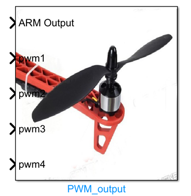
One-sentence Description: Sends specified PWM control signals to the I/O PWM output ports of PX4 hardware to drive actuators such as motors and servos; supports hardware-in-the-loop (HIL) simulation and real-flight scenarios.
This module belongs to the Sensors and Actuators interface library of the RflySim toolchain. It enables direct output control of PX4 hardware actuators by Simulink-based control algorithms and serves as a core module for connecting control outputs to underlying actuators in custom drone control algorithm development. The module supports user-defined configuration of PWM update rate and output channels, accommodating refresh frequency requirements of various actuators (e.g., electronic speed controllers (ESCs), servos), and can simultaneously control up to 8 PX4 hardware PWM output ports.
The module supports two operational modes: real-flight and hardware-in-the-loop simulation. When Publish Outputs is checked, it adapts to the RflySim platform’s HIL simulation workflow, working with CopterSim and RflySim3D to perform semi-physical simulation validation; when unchecked, it can be used directly for real-flight control of the PX4 flight controller. The module controls PWM output unlock/lock via the ARM input signal to ensure safe actuator startup. The input PWM signals are specified in microseconds (µs), conforming to the standard PWM output specification of PX4 hardware.
Port Descriptions
Input Ports (Inputs)
| Port Name | Data Type | Dimension | Description |
|---|---|---|---|
ARM Output |
boolean |
1×1 |
Unlocks/locks PWM outputs. PWM outputs are enabled when the signal is high (TRUE) and disabled when low (FALSE). When disabled, all PWM outputs are set to 900 µs (idle value) to prevent ESCs from entering timeout protection. |
PWM1 |
uint16 |
1×1 |
PWM signal value for PX4 hardware PWM output port 1, in microseconds (µs); typical range: 1000–2000 µs |
PWM2 |
uint16 |
1×1 |
PWM signal value for PX4 hardware PWM output port 2, in microseconds (µs); typical range: 1000–2000 µs |
PWM3 |
uint16 |
1×1 |
PWM signal value for PX4 hardware PWM output port 3, in microseconds (µs); typical range: 1000–2000 µs |
PWM4 |
uint16 |
1×1 |
PWM signal value for PX4 hardware PWM output port 4, in microseconds (µs); typical range: 1000–2000 µs |
PWM5 |
uint16 |
1×1 |
PWM signal value for PX4 hardware PWM output port 5, in microseconds (µs); typical range: 1000–2000 µs |
PWM6 |
uint16 |
1×1 |
PWM signal value for PX4 hardware PWM output port 6, in microseconds (µs); typical range: 1000–2000 µs |
PWM7 |
uint16 |
1×1 |
PWM signal value for PX4 hardware PWM output port 7, in microseconds (µs); typical range: 1000–2000 µs |
PWM8 |
uint16 |
1×1 |
PWM signal value for PX4 hardware PWM output port 8, in microseconds (µs); typical range: 1000–2000 µs |
Note: Only PWM ports that are enabled will display corresponding input ports in the module.
Output Ports (Outputs)
This module has no output ports.
Parameter Configuration (Parameters)
The following parameters can be configured in the Mask dialog box (double-click the module to open):
| Parameter Name | Type | Default Value | Available Values / Range | Description |
|---|---|---|---|---|
Publish Outputs |
bool |
true |
true / false |
When checked, the module supports hardware-in-the-loop simulation; when unchecked, it supports only real-flight scenarios. |
PWM update rate |
enum |
400Hz |
50Hz / 125Hz / 250Hz / 300Hz / 400Hz |
PWM signal refresh frequency (i.e., PWM update rate). |
Enable PWM1 |
bool |
true |
true / false |
Enables/disables PWM output port 1. |
Enable PWM2 |
bool |
true |
true / false |
Enables/disables PWM output port 2. |
Enable PWM3 |
bool |
true |
true / false |
Enables/disables PWM output port 3. |
Enable PWM4 |
bool |
true |
true / false |
Enables/disables PWM output port 4. |
Enable PWM5 |
bool |
false |
true / false |
Enables/disables PWM output port 5. |
Enable PWM6 |
bool |
false |
true / false |
Enables/disables PWM output port 6. |
Enable PWM7 |
bool |
false |
true / false |
Enables/disables PWM output port 7. |
Enable PWM8 |
bool |
false |
true / false |
Enables/disables PWM output port 8. |
Sample time |
double |
-1 |
> 0 | Module sample time in seconds. Default -1 indicates inheritance from the model’s sample time settings. |
Parameter Setting Notes
Publish Outputs
This parameter must be checked for hardware-in-the-loop simulation. When unchecked, the module supports only real-flight operation.
PWM update rate
The PWM update rate determines the refresh frequency of PWM signal transmission. PX4 defaults to 400 Hz. Different actuators require different update rates: ESCs typically require a higher update rate (e.g., 400 Hz) to ensure smooth control and fast response, whereas standard servos can operate with a lower update rate.
Enabling PWM Ports
Only PWM ports that are enabled will have corresponding input ports generated in the module. Unused ports can be disabled to hide their inputs; configure according to the actual number of PWM output ports used on the PX4 hardware.
ARM Output Input Description
Unlocking via a high-level ARM Output signal is a prerequisite for starting actuators such as motors. This input is typically controlled jointly by RC receiver signals and flight mode logic within the Simulink model. When ARM Output is low or during module initialization, all PWM outputs are set to 900 µs (idle value) to prevent ESCs from entering timeout protection due to lack of valid signals.
PWM Signal Value Description
The input PWM signal unit is microseconds (µs), with a typical range of 1000–2000 µs:
- 1000–1100 µs typically corresponds to minimum throttle or idle state,
- 1500 µs typically corresponds to the neutral position,
- 1900–2000 µs typically corresponds to maximum throttle.
Module Characteristics (Block Characteristics)
| Characteristic | Value |
|---|---|
| Supported Data Types | boolean, uint16, double, single |
| Direct Feedthrough | Yes |
| Sample Time | Discrete |
| Code Generation Support | Yes |
Data Communication Protocol
This module communicates with the PX4 flight controller hardware via the MAVLink protocol. After enabling the Publish Outputs option, PWM output data is transmitted via UDP to the simulation flight controller interface, following the default RflySim platform HIL simulation communication rules. The data format consists of 8 channels of 16-bit unsigned PWM values plus 1 unlock status flag, encapsulated into a MAVLink message for transmission.
Related Modules
| Module Name | Description |
|---|---|
RC_Input |
Reads PWM input signals from the RC receiver; can be used to obtain PWM control commands |
Servo_output |
Outputs servo control signals; belongs to the actuator output category of PX4 hardware modules |
GPS_Receiver |
Reads GPS positioning data; belongs to the sensor input category of the Sensors and Actuators library |
IMU_Reader |
Reads inertial measurement unit (IMU) data; belongs to the sensor input category of the Sensors and Actuators library |
Usage Example
For related usage examples, please refer to the following path:
``` [RflySim installation path]/RflySimAPIs/5.RflySimFlyCtrl/0.ApiExps/2.PSPOfficialExps/Readme