sensor_combined Module Documentation
Toolbox: Sensors and Actuators
Introduction
One-sentence Description: Retrieves combined native sensor data from the PX4 flight controller for use in developing custom drone control algorithms in Simulink.
This module belongs to the Sensors and Actuators interface library of the RflySim toolchain. It interfaces with the underlying sensor data from the PX4 flight controller (Pixhawk hardware), supporting flexible selection of outputs including magnetometer, accelerometer, gyroscope, barometer data, and timestamp since gyroscope startup. All output data are aligned to the NED coordinate system and provided with standard units, enabling direct use in development and validation of custom flight control algorithms.
This module requires the PX4 hardware to run the px4io service to obtain valid sensor signals. It can be used either with a real PX4 flight controller for hardware-in-the-loop simulation, or paired with CopterSim or RflySim3D for software-in-the-loop simulation. It serves as a core sensor interface module in the RflySim toolchain for supporting user-defined control algorithm development.
Port Descriptions
Input Ports (Inputs)
This module has no input ports.
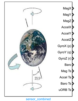
Output Ports (Outputs)
The output ports are determined by the configuration in the Output Selection region of the parameter dialog box. Enabling an option generates the corresponding output port:
| Port Name | Data Type | Dimension | Description |
|---|---|---|---|
Magnetometer |
single/double [to be confirmed] |
1×3 |
Magnetometer output: magnetic field data in the NED coordinate system, unit: Gauss |
Accelerometer |
single/double [to be confirmed] |
1×3 |
Accelerometer output: linear acceleration data in the NED coordinate system, unit: m/s² |
Gyroscope |
single/double [to be confirmed] |
1×3 |
Gyroscope output: angular velocity (p, q, r) in the body-fixed coordinate system, unit: rad/s |
Barometer |
single/double [to be confirmed] |
1×1 |
Barometer output: temperature-compensated pressure value, unit: millibar; alternatively, altitude can be output |
Timestamp |
double |
1×1 |
Timestamp output: elapsed time since gyroscope startup, unit: microseconds |
Parameter Configuration (Parameters)
The following parameters can be configured in the Mask dialog box opened by double-clicking the module:
| Parameter Name | Type | Default Value | Available Values/Range | Description |
|---|---|---|---|---|
CopterID |
int |
1 |
1~255 |
Assigned drone ID, used to retrieve sensor data for the corresponding drone |
Sample time |
double |
0.01 |
>0 |
Module sampling time, unit: seconds |
Magnetometer(x,y,z) |
bool |
false |
true/false |
Whether to output magnetometer data |
Accelerometer(x,y,z) |
bool |
false |
true/false |
Whether to output accelerometer data |
Gyroscope(x,y,z) |
bool |
false |
true/false |
Whether to output gyroscope data |
Barometer(Altitude) |
bool |
false |
true/false |
Whether to output barometer data |
uORB and RunTime(timestamp) |
bool |
false |
true/false |
Whether to output runtime timestamp |
Parameter Setting Notes
Output Selection Region
This region allows selecting the types of sensor data to be output. Each selected option automatically generates a corresponding output port, enabling flexible selection based on control algorithm requirements.
Sample time
This parameter sets the sampling frequency for reading sensor data. Typically, it should match the sensor output frequency of the PX4 flight controller. In simulation environments, the default value 0.01 can be retained.
CopterID
When multiple drones exist in the simulation scenario, this parameter specifies which drone’s sensor data the current module should retrieve. For single-drone simulations, the default value 1 is sufficient.
Module Characteristics (Block Characteristics)
| Characteristic | Value |
|---|---|
| Supported Data Types | double, single |
| Direct Feedthrough | No |
| Sample Time | Discrete |
| Code Generation Support | No |
Data Communication Protocol
The module communicates with the px4io service on the PX4 hardware side via UDP. It sends a sensor data request structure to port 20010 + drone ID on the remote IP. The request format follows the RflySim platform’s new VisionSensorReq protocol, with a fixed checksum of 12345 and a sensor type ID corresponding to the combined sensor identifier.
Related Modules
| Module Name | Description |
|---|---|
GPS_Recorder |
Outputs raw GPS positioning data |
rangefinder |
Outputs distance measurement data from ranging sensors |
airspeed |
Outputs airspeed sensor measurement data |
OpticalFlow |
Outputs motion measurement data from optical flow sensors |
Usage Examples
For relevant usage examples, refer to the following path:
Please refer to
Readme.pdfin the path above for complete example descriptions and operational steps.
Notes and Common Issues
- Initialization Dependency: This module requires the PX4 hardware to have the
px4ioservice running before it can obtain valid sensor data. Before launching simulation, ensure the PX4 service has started normally; otherwise, the output will remain at the initial zero value. - Multi-UAV Adaptation Note: When simulating multiple UAVs, this module automatically binds sensor data corresponding to the assigned ID. Ensure the target aircraft ID in the model configuration matches the actual PX4 flight controller number to avoid reading incorrect sensor data.
- Coordinate System Note: The magnetometer, accelerometer, and gyroscope data output by the module are all referenced to the NED coordinate system. When developing control algorithms, verify your algorithm’s coordinate system requirements to prevent control anomalies caused by coordinate system mismatches.
- Unit Consistency Note: Sensor output units conform to the native PX4 definitions: magnetometer units are in Gauss, acceleration units are in m/s², angular velocity units are in rad/s, barometric altitude corresponds to pressure units in millibars, and timestamp units are in microseconds. Do not perform additional unit conversions during use.
- Sampling Time Matching: The module’s sampling time should ideally match the actual sensor output frequency of the PX4 flight controller (e.g., the gyroscope typically outputs at 250 Hz, so the corresponding sampling time can be set to 0.004 s). Avoid excessively high sampling frequencies (which may cause redundant reads) or too low frequencies (which may introduce data delays and degrade control performance).
- Data Output Port Description: The number of module output ports is determined by the selections made in the
Output Selectionparameter interface. Output ports are generated only for the data types that are checked. If a required sensor output port is missing during use, verify the corresponding check state in the parameter configuration.
Changelog
v4.10(2024-08-12): Initial release. Supports acquisition of fused sensor data from PX4 hardware, with selectable outputs for magnetometer, accelerometer, gyroscope, barometer, and timestamp data.