RflySim3D Multimodal Sensor API Documentation
This document describes the parameter definitions for all multimodal sensors in RflySim.
Version Restriction Overview
| Version | Supported TypeIDs | Sensor Quantity Limit | Target Aircraft Limit |
|---|---|---|---|
| Free Edition (CurrentVersion < 6) | 1, 2, 3, 4, 5, 8, 10, 20, 21, 22, 23, 30, 31 | Max 3 (SeqID < 3) | Copter#1 only (except TargetMountType=4) |
| Full Edition (CurrentVersion ≥ 6) | All 18 types | Unlimited | Unlimited |
Full Edition Exclusive Sensors: Type 6 (Audio), Type 7 (Depth-to-Pointcloud), Type 9 (Gimballed Camera), Type 40 (Infrared Grayscale), Type 41 (Infrared Pseudo-Color).
Common Parameter Description (VisionSensorReqNew)
| Field | Type | Description |
|---|---|---|
checksum |
uint16 |
Data checksum, fixed to 12346 |
SeqID |
uint16 |
Sensor instance sequence ID (unique identifier) |
bitmask |
uint32 |
Reserved bitmask |
TypeID |
uint16 |
Sensor type ID (core of this document) |
TargetCopter |
uint16 |
Bound target aircraft ID (can be dynamically changed) |
TargetMountType |
uint16 |
Mounting mode (see detailed description below) |
DataWidth |
uint16 |
Data/image width (pixels or number of ray columns) |
DataHeight |
uint16 |
Data/image height (pixels or number of ray rows) |
DataCheckFreq |
uint16 |
Data update frequency (Hz), defaults to 30Hz when 0 |
SendProtocol[8] |
uint16[8] |
Transmission protocol parameters (see detailed description below) |
CameraFOV |
float |
Camera field of view (degrees), only valid for vision-type sensors |
SensorPosXYZ[3] |
float[3] |
Sensor mounting position (NED, meters) |
EulerOrQuat |
float |
>0.5 uses quaternion, ≤0.5 uses Euler angles |
SensorAngEuler[3] |
float[3] |
Sensor mounting Euler angles (Roll, Pitch, Yaw, degrees) |
SensorAngQuat[4] |
float[4] |
Sensor mounting quaternion (w, x, y, z) |
otherParams[16] |
float[16] |
Sensor-specific parameters (see each type description) |
Sensor Mounting Mode (TargetMountType)
| Value | Mode | Description |
|---|---|---|
| 0 | Fixed to Vehicle | Sensor moves with the vehicle (position + attitude follow) |
| 1 | Fixed to Vehicle Bottom | Similar to mode 0, but Z offset subtracts vehicle center height |
| 2 | World Fixed | Sensor position/attitude uses world absolute coordinates, does not follow any vehicle |
| 3 | Yaw Independent | Position follows vehicle, but Yaw attitude maintains world coordinate system |
| 4 | Attached to Sensor | Attached to another sensor; TargetCopter represents the target sensor's SeqID |
Data Transmission Mode (SendProtocol)
| Index | Field | Description |
|---|---|---|
[0] |
sendMode |
Transmission mode: 0=Shared Memory, 1=UDP Uncompressed, 2/3=UDP Video Stream |
[1-4] |
IP Address | When sendMode=1/2/3, specifies the target IP (four segments) |
[5] |
Port Number | When sendMode=1/2/3, specifies the target port |
[6] |
sendModeEx |
UDP fragment size (bytes). Valid range 100–60000, default 60000. Controls the payload size of each UDP packet |
[7] |
Function Flag | Meaning varies by type (see each sensor description) |
Note: Type 5, 7, 10, 20–23, 30, 31 do not support sendMode 2 and 3 (automatically downgraded to 1).
Sensor Type Detailed Parameters
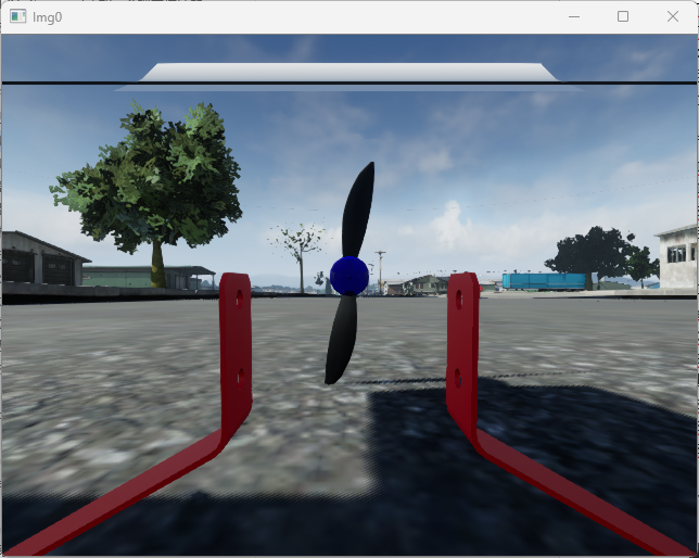
Type 1 — RGB Image
| Item | Description |
|---|---|
| Purpose | Capture color scene images |
| Acquisition Principle | Place a virtual camera at the sensor position, render the full-color image of the current perspective |
| Output Format | RGB color image (W×H×3 bytes) |
| DataWidth / DataHeight | Image resolution (pixels) |
| CameraFOV | Camera field of view (degrees) |
| otherParams | No dedicated parameters |
Config.json Example
{
    "VisionSensors": [{
        "SeqID": 0,              // Sensor sequence number, fill 0 for auto-increment
        "TypeID": 1,             // Sensor type: 1=RGB
        "TargetCopter": 1,       // Bound aircraft ID (Free Edition only supports #1)
        "TargetMountType": 0,    // Mounting mode: 0=Fixed to Vehicle
        "DataWidth": 640,        // Image width (pixels)
        "DataHeight": 480,       // Image height (pixels)
        "DataCheckFreq": 30,     // Data update frequency (Hz)
        "SendProtocol": [0,0,0,0,0,0,0,0], // [0]=Transmission mode (0:Shared Memory,1:UDP), [1-4]=IP, [5]=Port, [6]=Fragment size, [7]=Function bit
        "CameraFOV": 90,         // Field of view (degrees)
        "EularOrQuat": 0,        // 0=Euler angles, >0.5=Quaternion
        "SensorPosXYZ": [0.3, 0, 0],     // Mounting position offset (NED, meters)
        "SensorAngQuat": [0,0,0,0],      // Quaternion attitude (w,x,y,z)
        "SensorAngEular": [0,0,0],       // Euler angle attitude (Roll,Pitch,Yaw, degrees)
        "otherParams": [0,0,0,0,0,0,0,0,0,0,0,0,0,0,0,0]  // Dedicated parameters (no need to set for RGB)
    }]
}
Python Image Capture Demo
The following is the common image capture workflow for all image-type sensors (1, 2, 3, 4, 8, 40, 41). Subsequent sensors will only list the differences.
import VisionCaptureApi
import cv2, time, sys

vis = VisionCaptureApi.VisionCaptureApi()  # Can pass RflySim3D IP

# 1. Load Config.json
vis.jsonLoad()                  # Default loads Config.json in the same directory

# 2. Send image capture request to RflySim3D
if not vis.sendReqToUE4():
    sys.exit(0)

# 3. Start image capture thread
vis.startImgCap()

# 4. Loop to read images
while True:
    time.sleep(1/30.0)
    for i in range(len(vis.hasData)):
        if vis.hasData[i]:
            cv2.imshow('Img'+str(i), vis.Img[i])  # vis.Img[i]: np.ndarray (H×W×3, uint8, BGR)
            cv2.waitKey(1)

# Update sensor parameters in real-time
vs = vis.VisSensor[0]
vs.CameraFOV = 60
vs.SensorPosXYZ = [0.3, 0, 0]
vis.sendUpdateUEImage(vs)
Python Output: vis.Img[i] → np.ndarray (H×W×3, uint8, BGR color image)
ROS Data
| Topic | Message Type | Encoding |
|---|---|---|
/rflysim/sensor{SeqID}/img_rgb |
sensor_msgs/Image |
bgr8 |
ROS2 Distinction: ROS1 uses
rospy.Publisher; ROS2 usesnode.create_publisher+QoSProfile(depth=10, reliability=RELIABLE). Requires settingVisionCaptureApi.isEnableRosTrans = Trueto enable.
C++ ROS Subscription Demo
ROS1:
#include <ros/ros.h>
#include <sensor_msgs/Image.h>
#include <cv_bridge/cv_bridge.h>
#include <opencv2/highgui.hpp>

void imageCallback(const sensor_msgs::ImageConstPtr& msg) {
    cv::Mat img = cv_bridge::toCvShare(msg, "bgr8")->image;
    cv::imshow("RflySim RGB", img);
    cv::waitKey(1);
}

int main(int argc, char** argv) {
    ros::init(argc, argv, "rflysim_img_sub");
    ros::NodeHandle nh;
    // Modify topic name according to actual SeqID, e.g., /rflysim/sensor0/img_rgb
    ros::Subscriber sub = nh.subscribe("/rflysim/sensor0/img_rgb", 1, imageCallback);
    ros::spin();
    return 0;
}
ROS2:
#include <rclcpp/rclcpp.hpp>
#include <sensor_msgs/msg/image.hpp>
#include <cv_bridge/cv_bridge.h>
#include <opencv2/highgui.hpp>

class ImgSub : public rclcpp::Node {
public:
    ImgSub() : Node("rflysim_img_sub") {
        // ROS2 requires specifying QoS, consistent with SDK publisher
        auto qos = rclcpp::QoS(10)
            .reliability(rclcpp::ReliabilityPolicy::Reliable)
            .durability(rclcpp::DurabilityPolicy::TransientLocal);
        sub_ = create_subscription<sensor_msgs::msg::Image>(
            "/rflysim/sensor0/img_rgb", qos,
            [this](sensor_msgs::msg::Image::SharedPtr msg) {
                auto img = cv_bridge::toCvShare(msg, "bgr8")->image;
                cv::imshow("RflySim RGB", img);
                cv::waitKey(1);
            });
    }
private:
    rclcpp::Subscription<sensor_msgs::msg::Image>::SharedPtr sub_;
};

int main(int argc, char** argv) {
    rclcpp::init(argc, argv);
    rclcpp::spin(std::make_shared<ImgSub>());
    rclcpp::shutdown();
    return 0;
}
Note: The QoS of the ROS2 subscriber must match that of the SDK publisher (
Reliable+TransientLocal), otherwise messages will not be received. Replacesensor0in the topic name with the actualSeqID.Demo Example: [Installation Directory]\8.RflySimVision\0.ApiExps\1-UsageAPI\4.SendProtocolAPI
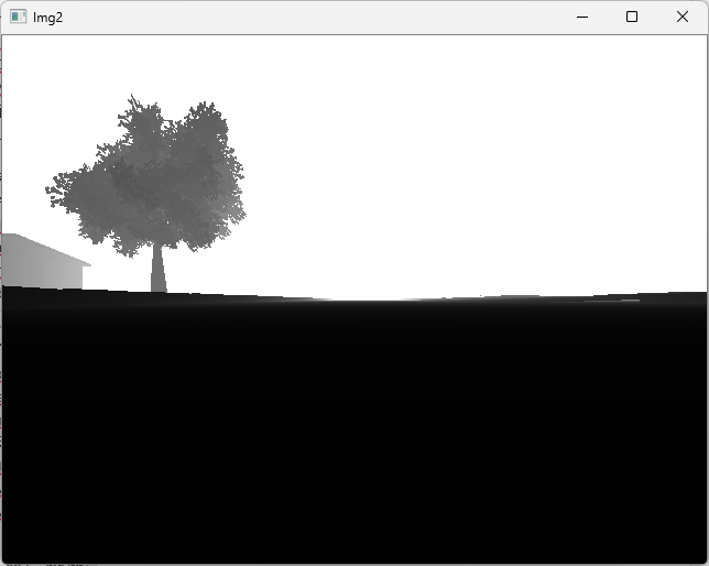
Type 2 — Depth Image
| Item | Description |
|---|---|
| Purpose | Obtain distance information from each pixel in the scene to the camera |
| Acquisition Principle | Place a virtual camera at the sensor location and render scene depth with floating-point precision |
| Output Format | 16-bit depth image (W×H×2 bytes) |
| DataWidth / DataHeight | Image resolution (pixels) |
| CameraFOV | Camera field of view (degrees) |
| otherParams | No dedicated parameters |
Python Output: vis.Img[i] → np.ndarray (H×W, uint16, 16-bit depth values). The image retrieval process is the same as Type 1, simply change TypeID to 2 in Config.json.
ROS: /rflysim/sensor{SeqID}/img_depth · sensor_msgs/Image · Encoding mono16
Demo Example: [Installation Directory]\8.RflySimVision\0.ApiExps\1-UsageAPI\1.ImgSenorAPI\3.DepthCameraDemo
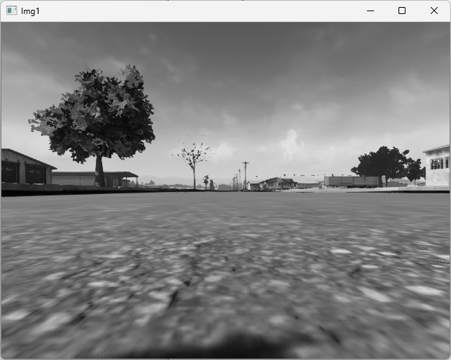
Type 3 — Grayscale Image
| Item | Description |
|---|---|
| Purpose | Capture single-channel grayscale scene images |
| Acquisition Principle | Place a virtual camera at the sensor location, render a color image, then convert to grayscale |
| Output Format | Single-channel grayscale (W×H×1 bytes) |
| DataWidth / DataHeight | Image resolution (pixels) |
| CameraFOV | Camera field of view (degrees) |
| otherParams | No dedicated parameters |
Python Output: vis.Img[i] → np.ndarray (H×W, uint8, single-channel grayscale). The image retrieval process is the same as Type 1, change TypeID to 3.
ROS: /rflysim/sensor{SeqID}/img_gray · sensor_msgs/Image · Encoding mono8
Demo Example: [Installation Directory]\8.RflySimVision\0.ApiExps\1-UsageAPI\4.SendProtocolAPI
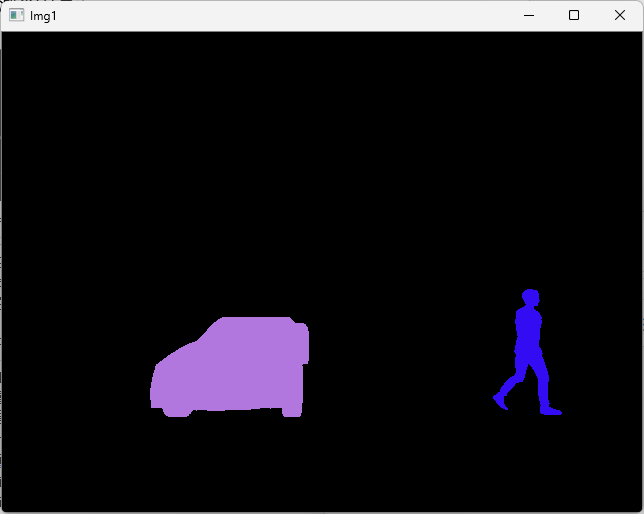
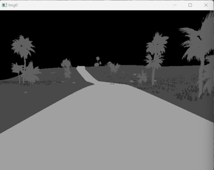
Type 4 — Segmentation Map
| Item | Description |
|---|---|
| Purpose | Semantic segmentation image where different objects in the scene are assigned different colors based on their annotation values |
| Acquisition Principle | Place a virtual camera at the sensor location and render colors based on the preset segmentation annotation value (CustomDepthStencilValue) of each object |
| Output Format | RGB color image (W×H×3 bytes) |
| DataWidth / DataHeight | Image resolution (pixels) |
| CameraFOV | Camera field of view (degrees) |
| otherParams | No dedicated parameters |
Python Output: vis.Img[i] → np.ndarray (H×W×3, uint8, BGR segmentation map). The image retrieval process is the same as Type 1, change TypeID to 4.
ROS: /rflysim/sensor{SeqID}/img_Segmentation · sensor_msgs/Image · Encoding bgr8
Demo Example: [Installation Directory]\8.RflySimVision\0.ApiExps\1-UsageAPI\1.ImgSenorAPI\5.SegmentImageDemo
Type 5 — Rangefinder Sensor
| Item | Description |
|---|---|
| Purpose | Single-ray distance measurement (forward) |
| Acquisition Principle | Emit a single ray forward from the sensor position, detect collision with scene objects, and return the distance |
| DataCheckFreq | Ranging frequency (Hz) |
| Shared Memory Size | 1 + 8 + 14×4 = 65 bytes |
otherParams Definition:
| Index | Parameter | Description |
|---|---|---|
[0] |
maxRange |
Maximum ranging distance (meters) |
Output Data Includes:
- Distance: Measured distance (meters), returns -1 if no hit
- disCopterID: CopterID of the hit target (-1 for non-aircraft targets)
- disData[0-2]: Emission point position (NED, meters)
- disData[3-5]: Sensor attitude angles (Roll, Pitch, Yaw, degrees)
- disData[6-8]: Hit point position (NED, meters)
- disData[9-11]: Hit target center position (NED, meters)
Python Output: vis.DistanceSensor → DistanceSensor object, containing .Distance (meters), .CopterID, .RayStart[3], .AngEular[3], .ImpactPoint[3], .BoxOri[3].
The rangefinder sensor is typically mounted on an image sensor using
TargetMountType=4to share its position and attitude.
Config.json Example (Mounted on RGB Camera)
{
    "VisionSensors": [
        {
            "SeqID": 0,
            "TypeID": 1,              // Create RGB camera first
            "TargetCopter": 1,
            "TargetMountType": 0,
            "DataWidth": 640,
            "DataHeight": 480,
            "DataCheckFreq": 30,
            "SendProtocol": [1,0,0,0,0,0,0,0],  // UDP mode
            "CameraFOV": 90,
            "EularOrQuat": 0,
            "SensorPosXYZ": [0.3, 0, 0],
            "SensorAngQuat": [0,0,0,0],
            "SensorAngEular": [0,0,0],
            "otherParams": [0,0,0,0,0,0,0,0,0,0,0,0,0,0,0,0]
        },
        {
            "SeqID": 0,
            "TypeID": 5,              // Rangefinder mounted on the RGB above
            "TargetCopter": 0,
            "TargetMountType": 4,     // MountType=4 attaches to sensor SeqID=0
            "DataWidth": 640,
            "DataHeight": 480,
            "DataCheckFreq": 30,
            "SendProtocol": [1,0,0,0,0,0,0,0],
            "CameraFOV": 90,
            "EularOrQuat": 0,
            "SensorPosXYZ": [0, 0, 0],
            "SensorAngQuat": [0,0,0,0],
            "SensorAngEular": [0,0,0],
            "otherParams": [200,0,0,0,0,0,0,0,0,0,0,0,0,0,0,0]  // maxRange=200m
        }
    ]
}
ROS: Rangefinder sensor data is not published as an independent ROS topic; it is accessed directly via the Python vis.DistanceSensor object.
Demo Example: [Installation Directory]\8.RflySimVision\0.ApiExps\1-UsageAPI\1.ImgSenorAPI\6.RangingImageDemo
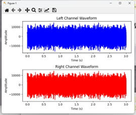
Type 6 — Audio Sensor (Under Development, Full Edition)
| Item | Description |
|---|---|
| Purpose | Environmental audio capture and analysis (e.g., ambient sound monitoring, sound source localization, speech recognition) |
| Acquisition Principle | Capture and output real-time audio data from the RflySim3D scene |
| Output Format | Real-time audio data stream (supports stereo, 48kHz sampling) |
| DataWidth / DataHeight | Invalid |
| CameraFOV | Invalid |
| Shared Memory Size | Shared memory not supported |
otherParams Definition:
| Index | Parameter | Description |
|---|---|---|
[0] |
enableAudio |
1: Enable and send audio data; 0: Stop sending audio data |
Network Communication Configuration (SendProtocol):
| Index | Field | Description |
|:-:|------|-------------|
| [0] | sendMode | 1: UDP transport protocol |
| [5] | Port Number | Destination port number for audio data transmission |
Config.json Example
{
    "VisionSensors": [
        {
            "SeqID": 0,
            "TypeID": 6,                    // Audio sensor
            "TargetCopter": 0,
            "TargetMountType": 0,
            "DataWidth": 0,
            "DataHeight": 0,
            "DataCheckFreq": 30,            // Transmission frequency
            "SendProtocol": [0,127,0,0,1,28003,0,0], // UDP port 28003
            "CameraFOV": 0,
            "EularOrQuat": 0,
            "SensorPosXYZ": [0, 0, 0],
            "SensorAngQuat": [0,0,0,0],
            "SensorAngEular": [0,0,0],
            "otherParams": [1,0,0,0,0,0,0,0,0,0,0,0,0,0,0,0] // 1: Enable transmission
        }
    ]
}
Python Output: Receive UDP data packets via a custom Socket (Buffer Size: 204800, stereo, 48kHz) for audio decoding or processing.
Demo Example: [Installation Directory]\4.RflySimModel\3.CustExps\e7_ExternalSensors\e2_Voice_PyRec
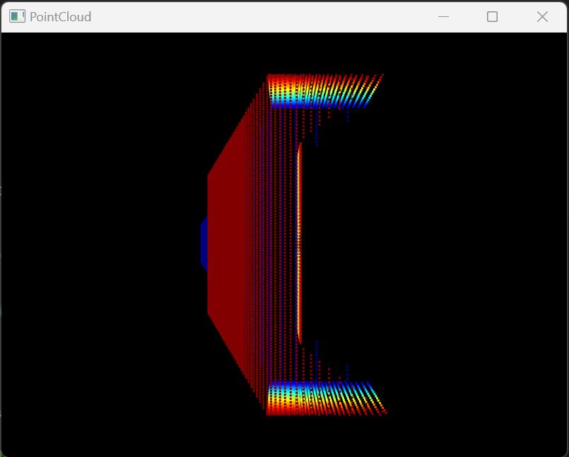
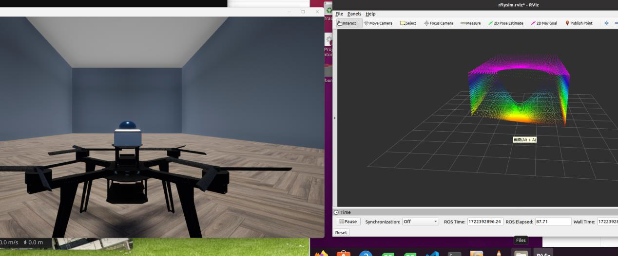
Type 7 — Depth to Point Cloud (Full Edition)
| Item | Description |
|---|---|
| Purpose | Generate 3D point cloud via depth image back-projection |
| Acquisition Principle | First render the scene depth image, then back-project each pixel into a 3D point using camera intrinsics (pinhole model), optionally obtaining semantic annotation colors for each point |
| Output Format | Int16-encoded XYZ [+ semantic color], 3 or 4 channels per point |
| Coordinate System | FLU (Front-Left-Up), relative to the reference frame set by AxisMask |
| DataWidth / DataHeight | Depth image resolution (pixels), affecting point cloud density |
| CameraFOV | Camera field of view (degrees) |
| Shared Memory Size | 1 + 8 + 9×4 + W×H×3×2 bytes |
otherParams Definition:
| Index | Parameter | Description |
|---|---|---|
[0] |
maxDepth |
Maximum depth distance (meters); points beyond this value are filtered out |
[1] |
step / debugMode |
When >0, enables debug mode (binds to DebugPlane display) and also serves as the sampling step |
[7] |
AxisMask |
Coordinate system mode (see table below) |
SendProtocol[7] Definition:
| Value | Meaning |
|---|---|
0 |
Output XYZ only (3 channels per point) |
>0 |
Output XYZI (4 channels per point), with the 4th channel being RGB555-encoded semantic color |
AxisMask Definition:
| Value | Mode | Description |
|---|---|---|
0 |
Vehicle Coordinates | Uses the absolute pose of the bound vehicle |
1 |
Sensor Absolute Coordinates | Uses the absolute pose of the sensor itself |
2 |
Sensor Relative Coordinates | Uses the pose change of the sensor relative to its starting point |
Python Output: vis.Img[i] → np.ndarray (N×3 or N×4, int16, XYZ[I] point cloud), can be displayed in real-time via the Open3DShow module. Image acquisition flow is the same as Type 1, with TypeID changed to 7.
ROS: Point cloud data is not published via the SDK's built-in ROS topics; users need to convert it to sensor_msgs/PointCloud2 themselves.
Demo Example: [Installation Directory]\8.RflySimVision\0.ApiExps\1-UsageAPI\3.PointCloudAPI\4.DepthPointCloudDemo
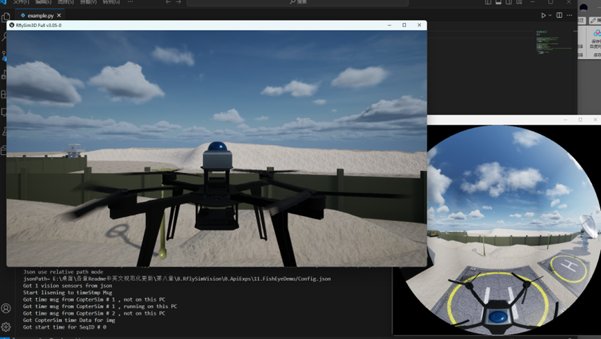
Type 8 — Fisheye Camera
| Item | Description |
|---|---|
| Purpose | Capture ultra-wide-angle / panoramic fisheye images |
| Acquisition Principle | Place a panoramic cube camera at the sensor location, render images in six directions simultaneously, then synthesize them into a single fisheye image using a fisheye projection model |
| Output Format | RGB color image (W×H×3 bytes) |
| DataWidth / DataHeight | Output image resolution |
| CameraFOV | Fisheye field of view |
otherParams Definition:
| Index | Parameter | Description |
|---|---|---|
[0] |
fisheyeType |
Fisheye projection type |
Python Output: vis.Img[i] → np.ndarray (H×W×3, uint8, BGR fisheye image). Image acquisition flow is the same as Type 1, with TypeID changed to 8.
ROS: /rflysim/sensor{SeqID}/fisheye · sensor_msgs/Image · encoding bgr8
Demo Example: [Installation Directory]\8.RflySimVision\0.ApiExps\11.FishEyeDemo
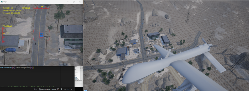
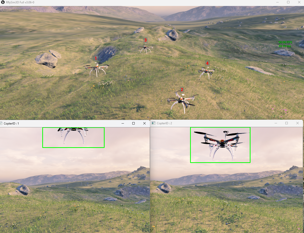
Type 9 — Gimbal Camera (Full Edition)
| Item | Description |
|---|---|
| Purpose | Controllable gimbal camera supporting attitude control, angular velocity control, target tracking, centering, optical zoom, ranging, and AI bounding box selection |
| Acquisition Principle | Uses a cinematic virtual camera to simulate the gimbal, achieving smooth motion via a spring arm component. Supports real-time orientation adjustment via control commands (quaternion Slerp interpolation), and can automatically lock onto a target or GPS coordinate for target tracking |
| Output Format | RGB color image (W×H×3 bytes) |
| DataWidth / DataHeight | Image resolution (pixels) |
| CameraFOV | Initial field of view (degrees), can be dynamically modified during runtime via bitmask |
Initialization Parameters (otherParams):
| Index | Parameter | Description |
|---|---|---|
[4] |
OpitcalBaseNum |
Optical zoom base number (range 4–1000, default 4) |
[5] |
disNum |
Maximum ranging distance (meters, default 200) |
Gimbal Control — bitmask
The gimbal is controlled via the VisionSensorReqNew.bitmask field, with each function corresponding to a bit. Multiple functions can be activated simultaneously.
| Bit | Function | Description |
|---|---|---|
1<<1 |
Field of View (FOV) | Directly sets the value of the CameraFOV field |
1<<2 |
Angle Control | Smoothly rotates the gimbal to the target attitude specified by SensorAngEuler / SensorAngQuat, moving via Slerp interpolation at 120°/s |
1<<3 |
Quaternion Mode | Used in conjunction with angle control; specifies the target attitude as a quaternion |
1<<4 |
Focal Length | Directly sets the focal length value (mm), passed via otherParams[0] |
1<<5 |
Center | Smoothly returns the gimbal to its initial mounting attitude (triggered when otherParams[1] > 0) |
1<<6 |
Angular Velocity Control | Continuously rotates at a specified angular velocity, set via otherParams[2] (Pitch) and otherParams[3] (Yaw) in °/s |
1<<7 |
Optical Zoom | Smoothly transitions the focal length to the target value of otherParams[4] × OpitcalBaseNum |
1<<8 |
Target Tracking | Automatically tracks a specified target. When otherParams[5] ≥ 0, tracks by CopterID; when otherParams[5] < 0, tracks by GPS coordinates (otherParams[9-11]) |
1<<9 |
Ranging | Emits a ray from the gimbal lens center, returning the hit distance and hit point coordinates |
1<<10 |
Image Type Switch | Switches the image type output by the gimbal, controlled by otherParams[7] (see table below) |
1<<11 |
AI Bounding Box | Enables AI target detection, controlled by otherParams[8] mode (see table below) |
Image Type Switch (otherParams[7])
| Value | Type | Description |
|---|---|---|
| 0 | RGB Color | Standard visible light image (default) |
| 1 | Infrared Pseudo-Color | Simulates infrared thermal imaging pseudo-color image |
| 2 | Infrared Grayscale | Simulates infrared imaging grayscale image |
AI Bounding Box Mode (otherParams[8])
| Value | Mode | Description |
|---|---|---|
| 0 | Off | No AI detection performed |
| 1 | Full Target Bounding Box | Automatically draws bounding boxes around all Copter objects in the field of view (excluding the own vehicle), returning bounding boxes |
| 2 | Pixel Selection | Detects the object at the pixel coordinates specified by otherParams[9-10], returns the bounding box of that object, and can be used as a tracking target |
Python Output: vis.Img[i] → np.ndarray (H×W×3, uint8, BGR). The gimbal is controlled using the VisionSensorReqNew structure (containing bitmask), with control commands sent via vis.sendUpdateUEImage(vsrNew).
ROS: /rflysim/sensor{SeqID}/img_cine · sensor_msgs/Image · encoding bgr8
Demo Example: [Installation Directory]\8.RflySimVision\2.AdvExps\e1_CameraKeyDemoOnUbuntu
Type 10 — Optical Flow Sensor
| Item | Description |
|---|---|
| Purpose | Optical flow velocity estimation + ground distance measurement |
| Acquisition Principle | Emits a ray towards the ground to measure ground distance; simultaneously compares pixel displacement between consecutive frames to estimate optical flow velocity. Supports ground truth mode (directly uses velocity data) and OpenCV mode (image feature point tracking) |
| Shared Memory Size | 1 + 8 + 8 + 1 + 4 + 8 + 1 + 12 = 43 bytes |
otherParams Definition:
| Index | Parameter | Description |
|---|---|---|
[0] |
maxRange |
Maximum ground distance measurement range (meters) |
[1] |
OpticalFlowType |
Optical flow calculation method: 0=Ground truth, 1=OpenCV |
[2] |
maxCorners |
(OpenCV only) Maximum number of corner points (default 50) |
[3] |
qualityLevel |
(OpenCV only) Corner quality threshold (default 0.3) |
[4] |
minDistance |
(OpenCV only) Minimum distance between corners (default 7 pixels) |
Output Data (OpticalFlowParams):
| Field | Description |
|---|---|
time_usec |
Unix timestamp |
sensor_id |
Sensor ID (= SeqID) |
flow_x / flow_y |
Optical flow velocity (dpix/frame) |
flow_comp_m_x / flow_comp_m_y |
Optical flow velocity (m/s) |
quality |
Optical flow quality (0–255) |
ground_distance |
Ground distance (meters) |
flow_rate_x / flow_rate_y |
Angular velocity compensation (rad/s) |
Python Output: Optical flow data is transmitted via the MAVLink protocol, obtained from the OpticalFlow data within the vis.imu related structures. Set TypeID to 10.
ROS: Optical flow data is not published via the SDK's built-in ROS topics; users need to use a MAVLink ROS bridge themselves.
Demo Example: [Installation Directory]\4.RflySimModel\3.CustExps\e7_ExternalSensors\e3_Opticalflow_UE
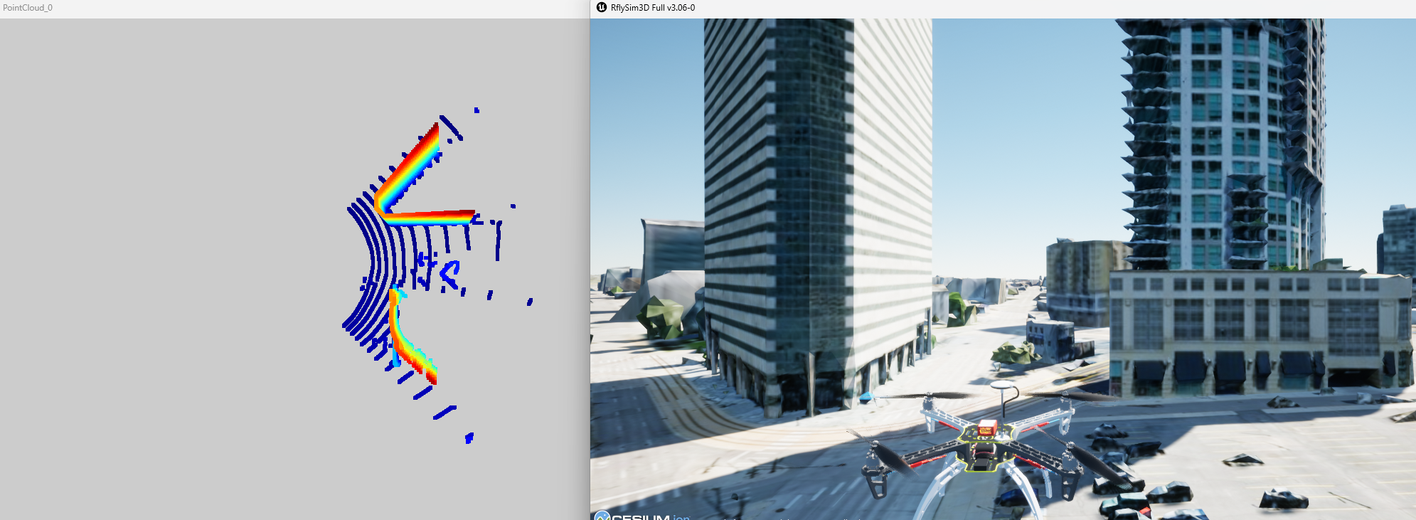
Type 20 — LiDAR (Body Frame)
| Item | Description |
|---|---|
| Purpose | Ray-tracing LiDAR simulation, outputting point cloud in the body frame |
| Acquisition Principle | Emits a large number of rays in parallel for collision detection according to the configured horizontal/vertical angular range and resolution, transforms hit point coordinates to the sensor body frame, and encodes the semantic annotation (RGB555) for each point |
| Output Format | Int16-encoded XYZI (4 channels per point) |
| Coordinate System | Body frame (sensor body) |
| Shared Memory Size | 1 + 8 + 9×4 + 2×4×W×H bytes |
otherParams Definition:
| Index | Parameter | Description |
|---|---|---|
[0] |
distRange |
Maximum ranging distance (meters), default 200m |
[1] |
distPrec |
Distance precision (reserved) |
[2] |
levelLeftAng |
Horizontal scan left boundary angle (degrees) |
[3] |
levelRightAng |
Horizontal scan right boundary angle (degrees) |
[4] |
horiDownAng |
Vertical scan lower boundary angle (degrees) |
[5] |
horiUpAng |
Vertical scan upper boundary angle (degrees) |
[6] |
GaussNoise0 |
Gaussian noise parameter 0 (reserved) |
[7] |
AxisMask |
Coordinate system mode (same as Type 7 AxisMask) |
SendProtocol[7] Definition:
| Value | Meaning |
|---|---|
0 |
Output XYZ only (skip intensity channel) |
>0 |
Output XYZI (4th channel is RGB555 semantic color) |
Scan Range: DataWidth columns × DataHeight rows, angular range defined by otherParams[2–5].
Python Output: vis.Img[i] → np.ndarray (N×3/4, int16, XYZI point cloud), displayable via Open3DShow module. Image retrieval process same as Type 1.
Config.json Example
{
    "VisionSensors": [{
        "SeqID": 0,
        "TypeID": 20,             // LiDAR body frame
        "TargetCopter": 1,
        "TargetMountType": 0,
        "DataWidth": 900,          // Horizontal scan 900 columns
        "DataHeight": 32,          // Vertical scan 32 rows
        "DataCheckFreq": 10,       // 10Hz
        "SendProtocol": [0,0,0,0,0,0,0,0],
        "CameraFOV": 90,
        "EularOrQuat": 0,
        "SensorPosXYZ": [0, 0, -0.3],  // Mounted 0.3m above vehicle
        "SensorAngQuat": [0,0,0,0],
        "SensorAngEular": [0,0,0],
        "otherParams": [200, 0.05, -45, 45, -20, 20, 0, 0, 0,0,0,0,0,0,0,0]
        // [0]=max distance 200m [2-5]=horizontal ±45° vertical -20°~+20°
    }]
}
ROS: Point cloud data is not published via SDK built-in ROS topics; users must convert it to sensor_msgs/PointCloud2 manually.
Demo Example: [Installation Directory]\8.RflySimVision\0.ApiExps\8.LidarAPIDemo\2.UDPDirectClientServer
Type 21 — LiDAR (World Frame)
Parameters are identical to Type 20, with the only difference:
| Item | Type 20 | Type 21 |
|---|---|---|
| Output Coordinate System | Body Frame | World Frame |
Python/ROS interface same as Type 20, change TypeID to 21.
Demo Example: [Installation Directory]\8.RflySimVision\0.ApiExps\8.LidarAPIDemo\3.UDPDirectClientServerType5
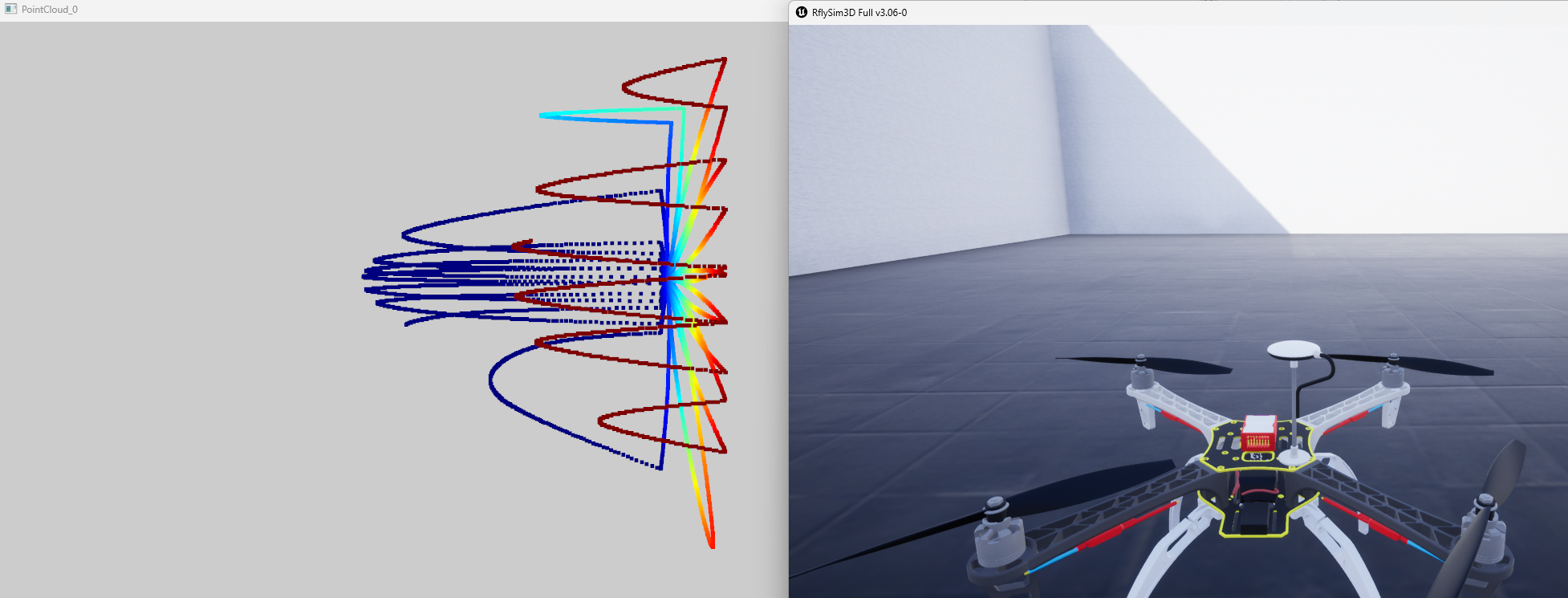
Type 22 — LiDAR (DJI Petal Scan)
| Item | Description |
|---|---|
| Purpose | DJI-style non-repeating petal scan LiDAR |
| Acquisition Principle | Simulates the figure-8 petal scan pattern of DJI Livox series, emitting rays along the petal path for collision detection each frame, accumulating multiple frames and outputting point clouds at the set frequency |
| Shared Memory Size | 1 + 8 + 9×4 + 2×4×W×H bytes |
otherParams Definition:
| Index | Parameter | Description |
|---|---|---|
[0] |
distRange |
Maximum ranging distance (meters), default 200m |
[1] |
d1 |
Arc chord height (difference between highest and lowest arc points) |
[2] |
xCor |
X-direction correction coefficient (default 1.4) |
[3] |
LeftRadCor |
Left arc radius correction coefficient (default 1.18) |
[4] |
EightNum |
Number of figure-8 petals (default 1) |
[5] |
FlowerNum |
Number of figure-8s per petal (default 1) |
[6] |
randAngle |
Random offset angle added to scan pattern (degrees) |
[7] |
AxisMask |
Coordinate system mode (same as Type 7 AxisMask) |
DataWidth / DataHeight Meaning Change:
- DataWidth: Total points per half petal
- DataHeight: Number of petal rows
- Actual scan points per frame = DataWidth × DataHeight × 3
- CameraFOV in this type is used for arc chord length calculation: Half chord length = CameraFOV / 4
Python/ROS interface same as Type 20, change TypeID to 22.
Demo Example: [Installation Directory]\8.RflySimVision\2.AdvExps\e0_AdvApiExps\.7LidarLivoxDemo
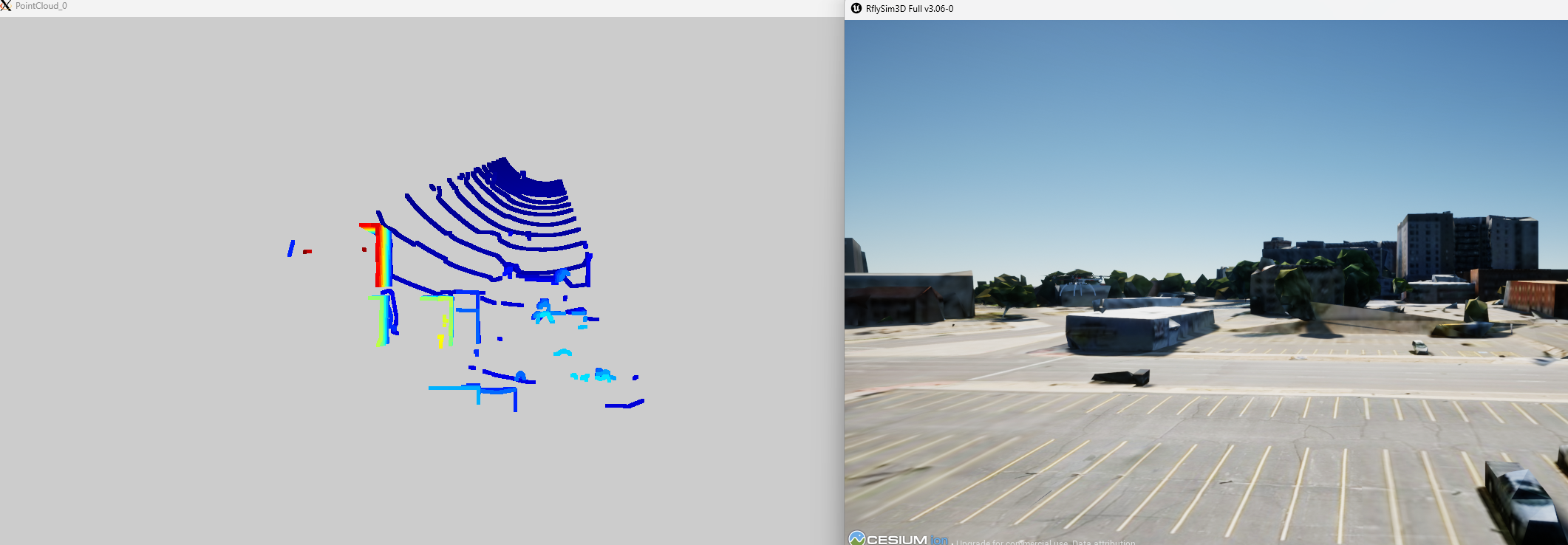
Type 23 — LiDAR Mid-360
| Item | Description |
|---|---|
| Purpose | Livox Mid-360 style 360° rotating scan LiDAR |
| Acquisition Principle | Simulates the 16-line rotating scan pattern of Livox Mid-360, emitting 17,408 rays (16×272×4) per frame for collision detection, rotating the scan angle frame by frame |
| Forced Resolution | DataWidth = 64, DataHeight = 272 (parameter changes ineffective) |
| Rays Per Frame | 16 × 272 × 4 = 17,408 rays |
| Shared Memory Size | 1 + 8 + 4×9 + 2×4×midPointNum bytes |
otherParams Definition:
| Index | Parameter | Description |
|---|---|---|
[0] |
distRange |
Maximum ranging distance (meters) |
Python/ROS interface same as Type 20, change TypeID to 23.
Demo Example: [Installation Directory]\8.RflySimVision\0.ApiExps\10.Mid360Demo
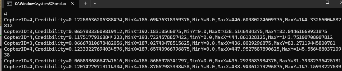
Type 30 — Simple Vision Sensor
| Item | Description |
|---|---|
| Purpose | Target detection within frustum, outputs 2D bounding boxes |
| Acquisition Principle | Determines target visibility via distance culling, frustum angle culling, and ray visibility checks, then projects the 3D bounding box of visible targets into screen space to output 2D rectangles |
| Shared Memory Size | 1 + 8 + 4 + maxTargets × sizeof(SimpleVisionDataStruct) bytes |
otherParams Definition:
| Index | Parameter | Description |
|---|---|---|
[0] |
maxRange |
Maximum detection distance (meters) |
[1] |
maxTargets |
Maximum number of targets (affects shared memory size) |
Output (SimpleVisionDataStruct):
| Field | Description |
|---|---|
CopterID |
Target aircraft ID |
Credibility |
Confidence (bounding box area ratio) |
BoxPositionInScreen |
Screen-space 2D bounding box (xMin, yMin, xMax, yMax) |
Python Output: vis.Img[i] → structured data containing CopterID, Credibility, BoxPositionInScreen. Image retrieval process same as Type 1, change TypeID to 30.
ROS: Detection data is not published via SDK built-in ROS topics; accessed directly via Python vis.Img[i].
Configuration Prerequisite
Type 30 Simple Vision Sensor must be written together with Type 1 RGB sensor in the same VisionSensors array of Config.json. If only Type 30 is configured without an RGB sensor, the SDK side cannot retrieve simple vision detection data.
Demo Example: [Installation Directory]\8.RflySimVision\2.AdvExps\e7_ObjDetectYolo\SimpleSensorBaseOnYolo
Type 31 — Simple Radar Sensor
| Item | Description |
|---|---|
| Purpose | Omnidirectional target detection, outputs relative target positions |
| Acquisition Principle | Detects all targets within a specified distance range, verifies line-of-sight via ray casting, outputs 3D relative positions of targets in the sensor coordinate system |
| Shared Memory Size | 1 + 8 + 4 + maxTargets × sizeof(SimpleRadarDataStruct) bytes |
otherParams Definition:
| Index | Parameter | Description |
|---|---|---|
[0] |
maxRange |
Maximum detection distance (meters) |
[1] |
maxTargets |
Maximum number of targets (affects shared memory size) |
Output (SimpleRadarDataStruct):
| Field | Description |
|---|---|
CopterID |
Target aircraft ID |
RelativePosition |
Relative position of target in sensor coordinate system (meters) |
Difference from Type 30: No frustum angle limitation (omnidirectional detection), no 2D projection.
Python Output: vis.Img[i] → list of targets, each element is (CopterID, PosX, PosY, PosZ). PosX/PosY/PosZ are the 3D relative positions of the target in the sensor coordinate system, in meters.
ROS: Detection data is not published via SDK built-in ROS topics; accessed directly via Python vis.Img[i].
Configuration Prerequisite
Type 31 Simple Radar Sensor must be written together with Type 1 RGB sensor in the same VisionSensors array of Config.json. If only Type 31 is configured without an RGB sensor, the SDK side cannot retrieve simple radar target data.
Config.json Example
The following example first creates a standard RGB sensor, then creates a simple radar sensor bound to the same aircraft. The output of Type 31 is still a list of target relative positions, but the configuration should retain the standard DataWidth, DataHeight, and CameraFOV fields; otherParams[0] is the maximum detection distance, and otherParams[1] is the maximum number of targets. Type 31 recommends using the UDP network transmission mode and setting an independent port for this sensor.
{
    "VisionSensors": [
        {
            "SeqID": 1, // Visual sensor sequence number. Set to 0 for automatic sequential numbering.
            "TypeID": 1, // 1: RGB Image
            "TargetCopter": 1, // CopterID to which the sensor is bound. Free version only supports binding to aircraft 1
            "TargetMountType": 0, // 0: Fixed to vehicle geometric center
            "DataWidth": 640,
            "DataHeight": 480,
            "DataCheckFreq": 10,
            "SendProtocol": [0, 0, 0, 0, 0, 0, 0, 0],
            "CameraFOV": 60,
            "EularOrQuat": 0,
            "SensorPosXYZ": [0.50, 0, 0.5],
            "SensorAngQuat": [0, 0, 0, 0],
            "SensorAngEular": [0, 0, 0],
            "otherParams": [0, 0, 0, 0, 0, 0, 0, 0, 0, 0, 0, 0, 0, 0, 0, 0]
        },
        {
            "SeqID": 2, // Simple radar sensor sequence number
            "TypeID": 31, // 31: Simple Radar
            "TargetCopter": 1,
            "TargetMountType": 0,
            "DataWidth": 640,
            "DataHeight": 480,
            "DataCheckFreq": 10,
            "SendProtocol": [1, 127, 0, 0, 1, 10001, 0, 0],
            "CameraFOV": 60,
            "EularOrQuat": 0,
            "SensorPosXYZ": [0.50, 0, 0.5],
            "SensorAngQuat": [0, 0, 0, 0],
            "SensorAngEular": [0, 0, 0],
            "otherParams": [200, 100, 0, 0, 0, 0, 0, 0, 0, 0, 0, 0, 0, 0, 0, 0]
            // Type 31 (Simple Radar): [0]=Maximum detection distance (m), [1]=Maximum number of targets
        }
    ]
}
Python Reading Example
import time
import VisionCaptureApi

vis = VisionCaptureApi.VisionCaptureApi()

# 1. Load Config.json containing Type 31
vis.jsonLoad()

# 2. Send sensor request to RflySim3D
if not vis.sendReqToUE4():
    raise RuntimeError("RflySim3D did not respond to sensor request")

# 3. Start shared memory/UDP data reading thread
vis.startImgCap()

# 4. Find the index of the Type 31 sensor in the VisSensor/Img array
radar_idx = next(
    i for i, sensor in enumerate(vis.VisSensor)
    if sensor.TypeID == 31
)

while True:
    time.sleep(0.05)
    if not vis.hasData[radar_idx]:
        continue

    # Type 31 output format:
    # vis.Img[radar_idx] = [
    #     (CopterID, PosX, PosY, PosZ),
    #     ...
    # ]
    # PosX/PosY/PosZ are the relative positions of the target in the sensor coordinate system, in meters.
    with vis.Img_lock[radar_idx]:
        targets = list(vis.Img[radar_idx])

    for copter_id, pos_x, pos_y, pos_z in targets:
        distance = (pos_x ** 2 + pos_y ** 2 + pos_z ** 2) ** 0.5
        print(
            f"CopterID={copter_id}, "
            f"RelativePosition=({pos_x:.2f}, {pos_y:.2f}, {pos_z:.2f}) m, "
            f"Distance={distance:.2f} m"
        )
Output Description
Type 31 is an omnidirectional relative position sensor; it does not perform field-of-view clipping and does not output 2D bounding boxes. If target bounding boxes within the image field of view are needed, please use Type 30 Simple Visual Sensor.
Type 40 — Infrared Grayscale Image (Full Edition)
| Item | Description |
|---|---|
| Purpose | Simulate grayscale images from infrared imaging |
| Acquisition Principle | Place a virtual camera at the sensor location, render the scene as a grayscale image simulating infrared radiation using infrared imaging materials |
| Output Format | Single-channel grayscale (W×H×1 bytes) |
| DataWidth / DataHeight | Image resolution (pixels) |
| CameraFOV | Camera field of view (degrees) |
| otherParams | No dedicated parameters |
Python Output: vis.Img[i] → np.ndarray (H×W, uint8, single-channel infrared grayscale). The image acquisition process is the same as Type 1, with TypeID changed to 40.
ROS: /rflysim/sensor{SeqID}/img_Infrared_Gray · sensor_msgs/Image · encoding mono8
Demo Example: [Installation Directory]\8.RflySimVision\0.ApiExps\1-UsageAPI\1.ImgSenorAPI\7.InfraredgrayThermalImageDemo
Type 41 — Infrared Thermal Color Image (Full Edition)
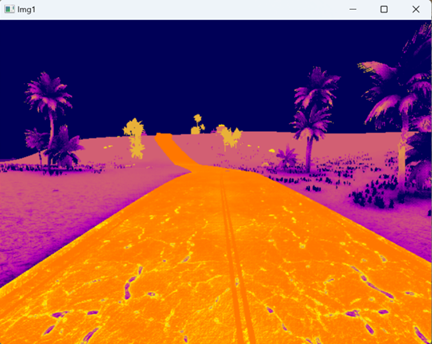
| Item | Description |
|---|---|
| Purpose | Simulate pseudo-color images from infrared thermal imaging (heatmap) |
| Acquisition Principle | Place a virtual camera at the sensor location, render the scene's temperature distribution as a pseudo-color image using infrared thermal imaging materials, with cold and hot areas displayed in different color tones |
| Output Format | RGB color image (W×H×3 bytes) |
| DataWidth / DataHeight | Image resolution (pixels) |
| CameraFOV | Camera field of view (degrees) |
| otherParams | No dedicated parameters |
Python Output: vis.Img[i] → np.ndarray (H×W×3, uint8, BGR infrared pseudo-color image). The image acquisition process is the same as Type 1, with TypeID changed to 41.
ROS: /rflysim/sensor{SeqID}/img_Infrared · sensor_msgs/Image · encoding bgr8
Demo Example: [Installation Directory]\8.RflySimVision\0.ApiExps\1-UsageAPI\1.ImgSenorAPI\7.InfraredgrayThermalImageDemo
IMU Sensor Data (from CopterSim)
IMU data is not generated by RflySim3D but is obtained via UDP from the CopterSim flight controller simulator. VisionCaptureApi provides a unified request and reception interface.
Data Structure (imuDataCopter)
| Field | Type | Description |
|---|---|---|
checksum |
int |
Checksum, fixed to 1234567898 |
seq |
int |
Message sequence number |
timestmp |
double |
Simulation timestamp (seconds) |
acc[3] |
float[3] |
Three-axis acceleration (m/s²), body coordinate system |
rate[3] |
float[3] |
Three-axis angular velocity (rad/s), body coordinate system |
C++ structure format:
2i1d6f, total size 40 bytes. CopterSim receives requests via UDP port30100 + (copterID-1)*2and sends responses back to port31000 + copterID - 1.
Python Request and Reading
import VisionCaptureApi

vis = VisionCaptureApi.VisionCaptureApi()
vis.jsonLoad()
vis.sendReqToUE4()
vis.startImgCap()

# Request IMU data from CopterSim for aircraft 1 (default 200Hz)
vis.sendImuReqCopterSim(copterID=1)

# Read IMU data
while True:
    if vis.hasIMUData:
        print('Time:', vis.imu.timestmp)       # Simulation time (seconds)
        print('Acceleration:', vis.imu.acc)     # [ax, ay, az] m/s²
        print('Angular Velocity:', vis.imu.rate) # [gx, gy, gz] rad/s
ROS Data
| Topic | Message Type | Description |
|---|---|---|
/rflysim/imu |
sensor_msgs/Imu |
Acceleration + angular velocity, frame_id = "imu" |
ROS Coordinate Mapping (Body → ROS):
| IMU Field | ROS linear_acceleration |
ROS angular_velocity |
|---|---|---|
[0] (x) |
-acc[0] |
rate[0] |
[1] (y) |
acc[1] |
-rate[1] |
[2] (z) |
-acc[2] |
-rate[2] |
ROS2 Distinction: ROS1 uses
rospy.Duration(imuStmp)to set the timestamp; ROS2 usesrclpy.duration.Duration(seconds=imuStmp)and assignsstamp.secandstamp.nanosecseparately.Demo Example: [Installation Directory]\RflySimAPIs\8.RflySimVision\0.ApiExps\1-UsageAPI\2.ImuSenorAPI
Appendix: Sensor Type Quick Reference Table
| TypeID | Name | Category | Free Edition | Acquisition Method | Output Format |
|---|---|---|---|---|---|
| 1 | RGB Image | Image | ✅ | Virtual camera rendering | RGB, 3ch |
| 2 | Depth Image | Image | ✅ | Virtual camera depth rendering | 16-bit, 2ch |
| 3 | Grayscale Image | Image | ✅ | Virtual camera rendering | Gray, 1ch |
| 4 | Segmentation Map | Image | ✅ | Semantic annotation rendering | RGB, 3ch |
| 5 | Rangefinder | Ray | ✅ | Ray collision detection | float distance |
| 6 | Audio | Audio | ❌ | Scene ambient sound capture | Audio stream |
| 7 | Depth Point Cloud | Point Cloud | ❌ | Depth map back-projection | XYZ[I], 3/4ch |
| 8 | Fisheye Camera | Image | ✅ | Panoramic camera + fisheye projection | RGB, 3ch |
| 9 | Gimballed Camera | Image | ❌ | Controllable gimbal camera | RGB, 3ch |
| 10 | Optical Flow | Sensor | ✅ | Ray + inter-frame image comparison | MAVLink optical flow |
| 20 | LiDAR (Body Frame) | Point Cloud | ✅ | Multi-ray parallel collision detection | XYZI, 4ch |
| 21 | LiDAR (World Frame) | Point Cloud | ✅ | Multi-ray parallel collision detection | XYZI, 4ch |
| 22 | LiDAR (DJI) | Point Cloud | ✅ | Petal scanning collision detection | XYZI, 4ch |
| 23 | Mid-360 | Point Cloud | ✅ | Rotating scanning collision detection | XYZI, 4ch |
| 30 | Simple Visual Sensor | Detection | ✅ | View frustum culling + ray detection | 2D BBox |
| 31 | Simple LiDAR Sensor | Detection | ✅ | Distance culling + ray detection | 3D relative position |
| 40 | Infrared Grayscale Image | Image | ❌ | Infrared imaging material rendering | Gray, 1ch |
| 41 | Thermal Color Image | Image | ❌ | Infrared thermal imaging rendering | RGB, 3ch |