Chapter 1: Introduction and System Architecture
Intelligent Unmanned Systems (IUS), as an interdisciplinary integration of cutting-edge technologies—including artificial intelligence, machine vision, and swarm intelligence—serve as a concentrated embodiment of contemporary technological advancement. This chapter systematically reviews the foundational theoretical framework and control principles of intelligent unmanned systems, introduces the basic architecture of the RflySim toolchain, and, taking multi-rotor drones as an example, outlines their assembly and debugging procedures, laying a solid theoretical and conceptual foundation for your subsequent in-depth learning.
1.1 Background and Theory
With the rapid development of cutting-edge technologies such as artificial intelligence, robotics, embodied intelligence, and autonomous driving, related concepts continue to emerge. Intelligent Unmanned Systems (IUS) build upon traditional unmanned systems by integrating artificial intelligence, endowing them with autonomous capabilities—including perception, reasoning, decision-making, and execution. Based on system scale and organizational complexity, IUS can be categorized into single-unit, formation, and swarm-cooperation systems, operating across underwater, terrestrial, and aerial platforms.

Despite the diversity of intelligent unmanned systems, their underlying concepts and architectures remain highly unified. Scientifically, they can be divided into six core modules: the airframe structure layer, the perception and localization layer, the control and decision-making layer, the actuation and execution layer, the environmental interaction layer, and the swarm collaboration layer. In spatial attitude estimation and control law design, the local navigation coordinate systems (NED / ENU) and the onboard front-right-down (FRD) coordinate system are widely adopted, with vehicle 3D spatial attitude precisely described using Euler angles or quaternions.

Taking multi-rotor drones as an example, a typical physical system comprises an airframe structure, a propulsion system (motors and propellers), a perception system (IMU and GNSS), an autopilot (flight control system), and a data link communication system. After assembly, the system must undergo rigorous steps—including firmware flashing, sensor calibration, power system testing, and field test flights—before it can be deployed for formal R&D experiments.


1.2 Framework and Interfaces
The RflySim toolchain supports full-stack development—from low-level control filtering to high-level intelligent perception—and enables smooth transitions (Sim2Real) from pure-software simulation (SITL) to hardware-in-the-loop simulation (HITL) and real hardware deployment.

1.2.1 Overview of the RflySim Toolchain
RflySim is a professional, open, and research- and education-oriented simulation and development toolchain for intelligent unmanned systems. Adhering to the core principles of Model-Based Design (MBD) and full hardware-in-the-loop coverage, it provides developers with an integrated development framework supporting multi-rotor, fixed-wing, and unmanned ground vehicle platforms, and natively supports large-scale swarm distributed adversarial simulations involving over 100 nodes.
1.2.2 Core Components and Interfaces
The daily operation of RflySim relies on the collaboration of multiple software components: the core simulation engine is CopterSim, a kinematic simulation engine; high-fidelity visual and physical simulation environments are built upon Unreal Engine / RflySim3D; and mission planning and low-level monitoring are handled by the QGroundControl ground station.
For developers, the platform offers not only a firmware-level automatic code generation channel—PX4PSP—based on MATLAB/Simulink for low-level development, but also a rich set of Python / ROS interface libraries (RflySimSDK) for upper-layer AI validation and development.

1.2.3 Recommended Learning Path
This course begins with foundational system theory and software operation (Chapters 1–2), guiding you into the construction of high-fidelity 3D environments and mathematical models for various vehicle platforms (Chapters 3–4). After mastering low-level filter design and the core flight control closed-loop (Chapters 5–7), you will advance to high-level practical applications—including multimodal perception, visual mapping, and swarm coordination and game-theoretic adversarial scenarios (Chapters 8–10).

1.3 Showcase of Advanced Cases
1.4 Course-Related Video Lectures
Lecture recordings for this chapter:
1.5 Chapter Experiment Cases
The verification experiments and guided case studies related to this chapter are located in the [Installation Directory]\RflySimAPIs\1.RflySimIntro folder.
1.5.1 Interface Learning Experiments
Located in the 1.RflySimIntro\0.ApiExps folder, these experiments cover foundational platform interface tutorials and general introductions to each tool.
Experiment 1: Introduction to RflySim Toolchain Companion Textbooks
- 📦 Version Requirement:
Free Edition - 📁 File Path: 1.RflySim_SupportBook/Readme.pdf
📝 Experiment Overview: Introduces companion textbook resources for the RflySim multirotor design and control platform, comprising 8 experimental tasks covering power systems, modeling, sensor calibration, filtering, and attitude control.
Experiment 2: PDF Document Collection and Merging Experiment
- 📦 Version Requirement:
Free Edition - 📁 File Path: 10.PDF_File_Processing/Readme.pdf
📝 Experiment Overview: Automates the collection, centralized archiving, and bookmarked merging of PDF documents across multiple experiment folders using Python, mastering the pathlib and pypdf libraries as well as natural sorting algorithms.
Experiment 3: Learning PX4 & Pixhawk Flight Control Systems
- 📦 Version Requirement:
Free Edition - 📁 File Path: 2.PX4&Pixhawk_Tutorials/Readme.pdf
📝 Experiment Overview: Provides learning materials for the PX4 open-source autopilot system, QGroundControl ground station software, and MAVLink communication protocol, enabling users to master basic Pixhawk flight controller operations, firmware flashing, parameter configuration, and communication protocol development.
Experiment 4: Python Beginner's Tutorial
- 📦 Version Requirement:
Free Edition - 📁 File Path: 3.Python_Tutorials/Readme.pdf
📝 Experiment Overview: Designed for absolute beginners, this experiment guides learners through 17 progressively structured tasks to systematically master core Python knowledge, including basic syntax, data structures, control flow, functions, library usage, file operations, exception handling, and object-oriented programming.
Experiment 5: MATLAB and Simulink Basics Tutorial
- 📦 Version Requirement:
Free Edition - 📁 File Path: 4.MATLAB&Simulink_Tutorials/Readme.pdf
📝 Experiment Overview: Learn the basic concepts and applications of MATLAB and Simulink, mastering their use in control system design, data analysis, algorithm development, and other areas.
Experiment 6: Visual Studio Basic Functions and Usage
- 📦 Version Requirement:
Free Edition - 📁 File Path: 5.MicrosoftVisualStudio_Tutorials/Readme.pdf
📝 Experiment Overview: Learn the basic functions, installation and configuration, project management, and debugging techniques of the Microsoft Visual Studio integrated development environment.
Experiment 7: 3Ds Max and Unreal Engine 3D Scene Construction
- 📦 Version Requirement:
Free Edition - 📁 File Path: 6.3DsMax&Unreal-Engine_Tutorials/Readme.pdf
📝 Experiment Overview: Learn the basic operations of 3Ds Max and Unreal Engine, mastering 3D modeling, rendering, and scene construction skills, and understanding their collaborative workflow.
Experiment 8: Linux Operating System Basics
- 📦 Version Requirement:
Free Edition - 📁 File Path: 7.Linux_Tutorials/Readme.pdf
📝 Experiment Overview: Learn the basic concepts, characteristics, and development history of the Linux operating system, mastering fundamental Linux knowledge and basic operations.
Experiment 9: ROS Tutorial
- 📦 Version Requirement:
Free Edition - 📁 File Path: 8.ROS_Tutorials/Readme.pdf
📝 Experiment Overview: Master the basic concepts and installation configuration of the ROS robot operating system, and understand the communication principles between MAVROS and the PX4 flight control system.
Experiment 10: RflySim Hardware System Configuration
- 📦 Version Requirement:
Free Edition - 📁 File Path: 9.HardwareSys_Introduction/Readme.pdf
📝 Experiment Overview: Introduces the configuration methods for Pixhawk series flight controller hardware (Pixhawk 2.4.8/6C/6X) and remote controllers (Tian Di Fei ET10, Foxeer FS-i6S) and other accessories, helping users master the basics of UAV hardware selection and setup.
1.5.2 Basic Usage Experiments
Located in the 1.RflySimIntro\1.BasicExps folder, these experiments provide a comprehensive set of supplementary textbook resources for beginners.
Experiment 1: Multicopter Design and Control Theory
- 📦 Version Requirement:
Free Edition - 📁 File Path: e1_MulticopterTheory/Readme.pdf
📝 Experiment Overview: Learn multicopter design, dynamic modeling, state estimation, and control theory, covering fundamental knowledge in aerodynamics, motor circuits, and structural materials.
Experiment 2: Multicopter Design and Control Practice
- 📦 Version Requirement:
Free Edition - 📁 File Path: e2_MulticopterPractice/Readme.pdf
📝 Experiment Overview: Conduct multicopter flight vehicle design and control experiments using the RflySim toolchain. This includes eight progressive experiments covering power system design, dynamic modeling, sensor calibration, filtering, attitude control, position control, semi-autonomous control, and fail-safe mechanisms, enabling mastery of the complete multicopter design and control workflow.
Experiment 3: Multicopter Flight Vehicle Design and Flight Experiment
- 📦 Version Requirement:
Free Edition - 📁 File Path: e3_MulticopterDesighFly/Readme.pdf
📝 Experiment Overview: Study the textbook “Multicopter Flight Vehicles: From Principles to Practice”, mastering fundamental concepts, flight principles, and system composition of multicopters, as well as becoming familiar with setting up simulation environments and configuring parameters in the RflySim toolchain.
Experiment 4: Multicopter Flight Vehicle Remote Control Practice
- 📦 Version Requirement:
Free Edition - 📁 File Path: e4_MulticopterRemoteCtrl/Readme.pdf
📝 Experiment Overview: This experiment focuses on remote control techniques for multicopter drones, achieving communication between ground stations and flight vehicles via network protocols. It covers principles of flight attitude and position control, and uses the RflySim simulation platform to validate control algorithms.
Experiment 5: Small Fixed-Wing UAV Flight Control Practice
- 📦 Version Requirement:
Free Edition - 📁 File Path: e5_SmallAircraftCtrlPractice/Readme.pdf
📝 Experiment Overview: A hands-on course on flight control for small fixed-wing UAVs. Through eight experiments covering UAV design, modeling, control, planning, and vision algorithms, it trains full-stack flight control development engineers using the RflySim toolchain.
Experiment 6: Python Fundamentals and VSCode Environment Setup
- 📦 Version Requirement:
Free Edition - 📁 File Path: e6_OverviewPython/Readme.pdf
📝 Experiment Overview: Designed for beginners with no prior experience, this experiment teaches how to configure the VSCode editor and Python environment on the RflySim platform, enabling learners to read and modify example source code, and acquire basic code debugging skills.
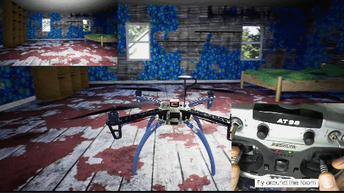
Experiment 7: Drone Tracking a Ball Experiment
- 📦 Version Requirement:
Free Edition - 📁 File Path: e7_RunPythonProject/Readme.pdf
📝 Experiment Overview: Implement a complete pipeline for a drone to visually track a red ball using Python. Learners will study Python fundamentals—including syntax, data structures, control flow, functions—and learn to use the OpenCV image processing library, as well as master RflySim platform API usage and drone control methods.
Experiment 8: Linux System Fundamentals
- 📦 Version Requirement:
Free Edition - 📁 File Path: e8_IntroductionLinux/Readme.pdf
📝 Experiment Overview: Introduce the characteristics, kernel versions, distributions, and file system structure of the Linux operating system, and guide learners through installing and using Ubuntu’s GUI and Windows WSL.
Experiment 9: Using WinWSL for Linux Command-Line Environment
- 📦 Version Requirement:
Free Edition - 📁 File Path: e9_LinuxCommandLine/Readme.pdf
📝 Experiment Overview: Learn to execute Python or shell scripts in an Ubuntu environment via WinWSL on Windows, enabling cross-platform development and seamless integration between Windows and Linux.
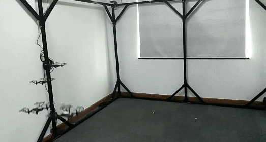
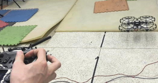
Experiment 10: Assembly and Debugging of a Quadcopter Drone
- 📦 Version Requirement:
Free Edition - 📁 File Path: e10.DroneAssTutorial/1.QuadUAVAss/Readme.pdf
📝 Experiment Overview:
Learn and master the assembly and tuning process of quadrotor UAVs, including the composition and functionality of core subsystems such as the airframe structure, power system, and flight control system. Study component selection, installation, and configuration methods, and acquire fundamental flight operation skills and safety protocols.
Experiment 11: Fixed-Wing UAV Assembly and Simulation
- 📦 Version Requirement:
Free Edition - 📁 File Path: e10.DroneAssTutorial/3.FWAss/Readme.pdf
📝 Experiment Overview:
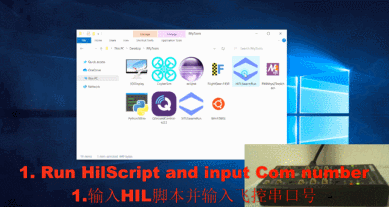
Introduce the fixed-wing UAV assembly process, covering three scenarios: Software-in-the-Loop (SIL) simulation, Hardware-in-the-Loop (HIL) simulation, and physical assembly. Learn to use the RflySim toolchain for fixed-wing UAV testing.
1.5.3 Advanced Development Experiments
Stored in the 1.RflySimIntro\2.AdvExps folder, these experiments further familiarize users with the configuration of certain low-level firmware ecosystems.
Experiment 1: Flight Controller ETH Port Configuration
- 📦 Version Requirement:
Free Edition - 📁 File Path: e9.ConfigTools/e1.FCUETH_NetConfig/Readme.pdf
📝 Experiment Overview: Learn to configure the ETH port of Pixhawk V6X-series flight controllers as a MAVLink communication interface, enabling high-speed data communication between the flight controller and RflySim simulation software via Ethernet. Master network configuration techniques for multi-robot swarm simulation environments.
Experiment 2: RflySim Remote Controller Configuration
- 📦 Version Requirement:
Free Edition - 📁 File Path: e1.RCIntro/Readme.pdf
📝 Experiment Overview: This experiment introduces the hardware configuration and usage of remote controllers on the RflySim platform, including configuration procedures for models such as the Foxeer FS-i6S, Tian Di Fei ET10, and Tian Di Fei AT9S Pro. Master the connection methods between remote controllers and computers, as well as communication protocol configuration, to ensure seamless communication and interaction between the remote controller and the RflySim toolchain.
Experiment 3: RflySim Toolchain Flight Controller Hardware Configuration
- 📦 Version Requirement:
Free Edition - 📁 File Path: e2.FCUIntro/Readme.pdf
📝 Experiment Overview: This experiment introduces hardware configuration methods for Pixhawk-series flight controllers on the RflySim platform, including firmware flashing, QGC parameter settings, and HIL simulation configuration. The goal is to master the setup of hardware-in-the-loop simulation environments.
Experiment 4: Feisi Swarm Simulation Unit ETH Port Configuration
- 📦 Version Requirement:
Free Edition - 📁 File Path: e9.ConfigTools/e2.FeisiSwarmBox_Config/Readme.pdf
📝 Experiment Overview: Explain how to configure the ETH port of Pixhawk V6X flight controllers within the Feisi Swarm Simulation Unit to enable hardware-in-the-loop (HITL) simulation for up to 10 aircraft. Steps include router network configuration, flight controller firmware flashing, and automated parameter configuration using the NetSimAutoConfig.py script.
Experiment 5: Modifying PX4 Flight Controller Vehicle Frame via Ethernet Port
- 📦 Version Requirement:
Free Edition - 📁 File Path: e9.ConfigTools/e3.FCUETH_ModifyParam/Readme.pdf
📝 Experiment Overview:
Use Python scripts and the MAVLink protocol to remotely modify the PX4 flight controller’s SYS_AUTOSTART parameter, switching the vehicle frame from quadrotor to fixed-wing (2100). Validate the configuration results using hardware-in-the-loop simulation, and master automated flight controller parameter configuration techniques.
Experiment 6: RflySim Python Development Environment Configuration
- 📦 Version Requirement:
Free Edition - 📁 File Path: e3.PythonConfig/Readme.pdf
📝 Experiment Overview: Learn how to configure the RflySim Python runtime environment in VSCode/PyCharm, and understand the principles of Python dependencies and the underlying API mechanisms.
Experiment 7: RflySim Platform Computer Hardware Requirements
- 📦 Version Requirement:
Free Edition - 📁 File Path: e4.ComputerIntro/Readme.pdf
📝 Experiment Overview: Introduce the computer hardware requirements for running the RflySim platform, covering recommended configurations for three scenarios: smooth operation, full platform functionality, and flight controller development.
Experiment 8: RflySim UAV Hardware Configuration
- 📦 Version Requirement:
Free Edition - 📁 File Path: e5.UAVConnfig/Readme.pdf
📝 Experiment Overview: Based on the RflySim platform, learn the recommended configuration and usage methods for UAV hardware systems, including assembly and debugging of the Feisi MiniQuad 150 UAV development platform, and master hardware-in-the-loop simulation connection methods for flight controllers such as Pixhawk.
Experiment 9: Visual Studio Installation and Configuration
- 📦 Version Requirement:
Free Edition - 📁 File Path: e6.VisualStudioInstall/Readme.pdf
📝 Experiment Overview: Learn the installation and configuration of Visual Studio 2017 and 2022, and master the setup of the MATLAB Compiler environment to prepare for generating DLL files in the RflySim toolchain.
Experiment 10: Flight Controller Ethernet Simulation Configuration
- 📦 Version Requirement:
Free Edition - 📁 File Path: e9.ConfigTools/Readme.pdf
📝 Experiment Overview: Learn how to configure the Ethernet simulation functionality of the Pixhawk 6x flight controller using the RflySim toolchain, and master the setup methods for flight controller network communication.
Experiment 11: WSL2 GPU Acceleration Configuration
- 📦 Version Requirement:
Free Edition - 📁 File Path: e11.WSL2_GPUAccConfig/Readme.pdf
📝 Experiment Overview: This experiment teaches how to configure GPU-accelerated computing in the WSL 2 environment, including CUDA toolkit installation, deployment of the PyTorch GPU version, GPU utilization within Docker containers, and performance validation—laying the foundation for GPU-accelerated simulation on the RflySim platform.
Experiment 12: ROS2 Shared Memory Zero-Copy Performance Validation
- 📦 Version Requirement:
Free Edition - 📁 File Path: e12.ROS2SharedMem/Readme.pdf
📝 Experiment Overview: Validate the performance advantages of ROS2 shared memory and zero-copy mechanisms in image transmission, comparing them with traditional network transmission methods to demonstrate reduced latency and decreased CPU resource consumption.
Experiment 13: WinWSL2-GPU Environment Installation and Configuration
- 📦 Version Requirement:
Free Edition - 📁 File Path: e13.WinWSL2-GPU/Readme.pdf
📝 Experiment Overview: This experiment teaches how to install and configure a WSL 2 environment on Windows to support GPU acceleration. Students will learn the differences between WSL 1 and WSL 2, install GPU-accelerated environments such as CUDA and PyTorch, validate GPU acceleration functionality, test performance improvements in large matrix operations, and master both external installation and overlay installation methods.
Experiment 14: Local Deployment and Usage of Large Language Models
- 📦 Version Requirement:
Free Edition - 📁 File Path: e14.LocalLLMDepUse/Readme.pdf
📝 Experiment Overview: Deploy the Ollama large language model service locally and offline in the WinWSL 2-GPU environment, and implement an end-to-end practical workflow for UAV mission control using the lightweight qwen3:0.6b model.
Experiment 15: QGC Log Download
- 📦 Version Requirement:
Free Edition - 📁 File Path: e10.Log-GetAnalysis/1.LogGet/Readme.pdf
📝 Experiment Overview: Download UAV flight logs via the QGroundControl ground station software, master the log acquisition method, and prepare for subsequent log analysis.
Experiment 16: Real-Time Acquisition of UAV Flight Status Using Python
- 📦 Version Requirement:
Free Edition - 📁 File Path: e10.Log-GetAnalysis/10.UAVsStatusRTGet_Py/Readme.pdf
📝 Experiment Overview:
Implement real-time acquisition and analysis of UAV flight logs using Python. Learn to use the mav.InitTrueDataLoop() interface to monitor true data (Euler angles, angular velocity, velocity, position, etc.) and store it for analysis.
Experiment 17: Real-Time Acquisition of UAV Flight Status Using Simulink
- 📦 Version Requirement:
Free Edition - 📁 File Path: e10.Log-GetAnalysis/11.UAVsStatusRTGet_Mat/Readme.pdf
📝 Experiment Overview: This experiment uses Simulink to achieve real-time acquisition, storage, and analysis of UAV flight logs, including Software-in-the-Loop (SITL) and Hardware-in-the-Loop (HITL) simulations. Learn flight data collection and analysis methods.
Experiment 18: Custom uORB Message Logging
- 📦 Version Requirement:
Free Edition - 📁 File Path: e10.Log-GetAnalysis/12.CusuORBmsgLog/Readme.pdf
📝 Experiment Overview: Record and analyze controller variables (such as roll, pitch angle, and angular velocity) through custom uORB messages. This includes four steps: automatic code generation firmware, HIL simulation, log download, and log parsing, helping to optimize controller performance.
Experiment 19: Learning Log Analysis Methods with Flight Review
- 📦 Version Requirement:
Free Edition - 📁 File Path: e10.Log-GetAnalysis/2.LogAnalysis_Wed/Readme.pdf
📝 Experiment Overview: Learn UAV flight log analysis methods through the Flight Review website. Master attitude curve tracking analysis and motor PWM output analysis methods to evaluate UAV flight performance and PID tuning status.
Experiment 20: CMD Flight Log Analysis
- 📦 Version Requirement:
Free Edition - 📁 File Path: e10.Log-GetAnalysis/3.LogAnalysis_CMD/Readme.pdf
📝 Experiment Overview: Learn to use the pyulog tool in the CMD environment to convert .ulg flight log files to .csv format, and master the basic methods of flight log analysis.
Experiment 21: MATLAB Log Analysis Experiment
- 📦 Version Requirement:
Free Edition - 📁 File Path: e10.Log-GetAnalysis/4.LogAnalysis_Mat/Readme.pdf
📝 Experiment Overview:
Learn to use RflySim's ulog2csv function to convert .ulg logs to .csv format, and use the MATLAB Flight Log Analyzer application for flight log analysis, plotting attitude angle comparison charts, and saving graphics.
Experiment 22: Python Log Analysis
- 📦 Version Requirement:
Free Edition - 📁 File Path: e10.Log-GetAnalysis/5.LogAnalysis_Py/Readme.pdf
📝 Experiment Overview: Learn to use Python to parse ULog format flight controller logs, extract attitude data, and visually display the comparison between actual and expected values. Master the basic workflow and methods of log analysis.
Experiment 23: PlotJuggler Log Analysis
- 📦 Version Requirement:
Free Edition - 📁 File Path: e10.Log-GetAnalysis/6.LogAnalysis_PlotJuggler/Readme.pdf
📝 Experiment Overview: Learn to use PlotJuggler software to analyze UAV flight logs, mastering graphical analysis methods such as log import, message data viewing, and attitude angle curve plotting.
Experiment 24: Binary Log Recording and Reading Experiment
- 📦 Version Requirement:
Free Edition - 📁 File Path: e10.Log-GetAnalysis/8.CusmsgSDLog/Readme.pdf
📝 Experiment Overview:
Use the binary_logger binary log module to complete flight data writing to an SD card and reading analysis, mastering the underlying log operation mechanism of the PX4 flight controller.
Experiment 25: Multi-UAV SIL Simulation Log Acquisition
- 📦 Version Requirement:
Free Edition - 📁 File Path: e10.Log-GetAnalysis/9.SwarmLogGet/Readme.pdf
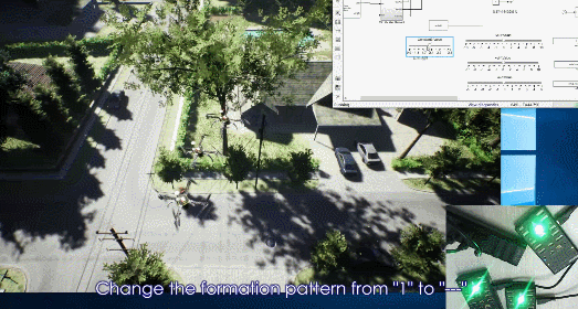
📝 Experiment Overview: Learn to automatically record .ulg format logs in a 4-UAV SIL simulation and analyze UAV flight performance and behavior.
Experiment 26: Radiodetection AT9S Pro Remote Controller Configuration
- 📦 Version Requirement:
Free Edition - 📁 File Path: e1.RCIntro/AT9S_Pro/Readme.pdf
📝 Experiment Overview: Introduce the configuration method for the Radiodetection AT9S Pro 12-channel remote controller, including multi-rotor mode setting, throttle reverse, channel mapping, and remote controller calibration, for UAV flight control.
Experiment 27: Foxeer i6S Remote Controller Configuration
- 📦 Version Requirement:
Free Edition - 📁 File Path: e1.RCIntro/FS_i6S/Readme.pdf
📝 Experiment Overview: Introduce the hardware configuration, functional interfaces, joystick switches, and status indicator usage of the FS-i6S transmitter and FS-iA6B receiver, suitable for learning remote control of multi-rotor and racing drone models.
Experiment 28: Tian Di Fei ET10 Remote Controller Configuration and Flight Mode Settings
- 📦 Version Requirement:
Free Edition - 📁 File Path: e1.RCIntro/WELY_ET10/Readme.pdf
📝 Experiment Overview: Introduce the product features of the Tian Di Fei ET10 remote controller and the calibration method for multi-rotor UAV remote controllers, including channel configuration for SA-SD, SE switches, and the V1 knob, as well as the switching settings for three flight modes: Stabilize, Altitude Hold, and Position Hold.
1.5.4 Advanced Development Experiments
No experiment cases available yet.