SensorOutput Module Documentation
Toolbox: RflySim Model
Introduction
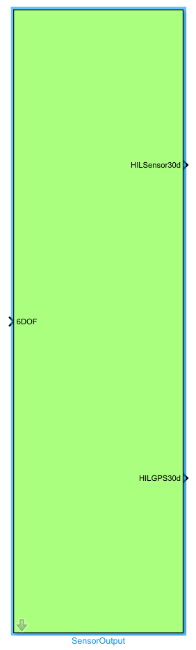
One-sentence Description: Integrates sensor and GPS models to generate hardware-characteristic-compliant sensor and GPS signals based on the 6-DOF vehicle motion state, feeding them back to the PX4 flight controller.
This module is the core component of the RflySim Model toolbox responsible for simulating sensor perception, providing realistic sensor data inputs for PX4 flight controller hardware-in-the-loop (HIL) simulation. It receives the true 6-DOF vehicle motion state bus output from the 6DOF module, generates noisy sensor outputs using built-in noise models, and supports adjusting the global noise gain via parameters to simulate sensors of varying accuracy levels.
The module outputs the HILSensor30d sensor signal collection and HILGPS30d GPS signal, which are transmitted to the PX4 flight controller via RflySim’s HIL interface to complete the closed-loop simulation. Simultaneously, it provides foundational state data for visualization in CopterSim and RflySim3D. As a critical bridge connecting dynamics simulation and flight control logic in the entire UAV simulation loop, this module can be directly applied to flight control algorithm simulation and validation scenarios for various UAV types, including multirotors and fixed-wing aircraft.
Port Descriptions
Input Ports
| Port Name | Data Type | Dimension | Description |
|---|---|---|---|
6DOF |
double |
1×13 |
6-DOF bus signal output by the 6DOF module, containing vehicle position, attitude, linear velocity, angular velocity, and other motion state information [To be confirmed] |
Output Ports
| Port Name | Data Type | Dimension | Description |
|---|---|---|---|
HILSensor30d |
double |
1×30 |
30-dimensional vector outputting noisy sensor signals, compatible with the PX4 HIL simulation interface |
HILGPS30d |
double |
1×30 |
30-dimensional vector outputting noisy GPS signals, compatible with the PX4 HIL simulation interface |
Parameter Configuration
The following parameters can be configured in the Mask dialog box opened by double-clicking the module:
| Parameter Name | Type | Default Value | Available Values/Range | Description |
|---|---|---|---|---|
Param_GlobalNoiseGainSwitch |
double |
1 |
0~1 |
Global noise gain for sensor outputs, used to control the intensity of sensor noise |
Parameter Setting Description
Param_GlobalNoiseGainSwitch
This parameter controls the global intensity of noise in all sensor outputs, with a value range of 0~1: when set to 0, all sensor noise is disabled, yielding ideal noise-free sensor signals; when set to 1, the module outputs noise at the default simulated intensity, closely mimicking real-world sensor behavior.
Module Characteristics
| Characteristic | Value |
|---|---|
| Supported Data Types | double, single |
| Direct Feedthrough | Yes |
| Sample Time | Inherited |
| Code Generation Support | No |
Data Communication Protocol
This module does not involve network communication.
Related Modules
| Module Name | Description |
|---|---|
SixDOF |
Computes 6-DOF vehicle kinematics and outputs the 6DOF bus signal to the SensorOutput module |
PX4Controller |
Receives sensor and GPS signals from the SensorOutput module to implement flight control closed-loop |
HIL_GPS_Simulink |
Works with PX4 HIL simulation to process GPS sensor data output |
HIL_Sensor_Simulink |
Works with PX4 HIL simulation to process inertial and other sensor data output |
Notes and Common Issues
- Initialization Order: This module must be placed after the 6DOF module and before the PX4 controller input module. Before simulation starts, ensure the 6DOF module has completed initialization of the vehicle’s initial state; otherwise, sensor outputs may be all zeros or otherwise abnormal.
- Sample Time Matching: The module’s sample time must match the sample time of the connected PX4 controller HIL interface. Typically, it should be set to 1 ms or equal to the simulation step size. Mismatched sample times can cause timing errors in PX4 flight control calculations, leading to attitude control divergence.
- Noise Parameter Setting: The
Param_GlobalNoiseGainSwitchparameter is strictly limited to the range0~1. Values outside this range will cause the simulation to abort with an error. Setting it to0disables sensor noise, suitable for open-loop testing; setting it to1enables full-intensity noise to simulate realistic sensor noise characteristics. - Input Signal Validation: This module only recognizes standard 6DOF bus input signals. Feeding it custom-modified state signals will result in sensor data parsing errors and abnormal
HILSensor30dandHILGPS30dvector outputs. - PX4 Compatibility Note: The
HILSensor30dandHILGPS30doutput formats are fully compatible with the native PX4 HIL interface. When interfacing with a custom-modified PX4 flight control firmware, manually verify that signal dimensions and ordering match. - GPS Signal Troubleshooting: If GPS output remains constantly zero during simulation, first verify that the 6DOF module correctly outputs latitude, longitude, and altitude position data; second, confirm that the correct simulation scene start-point parameters were loaded during module initialization.
Changelog
v4.0.0(2024-01-01): Initial release. Implemented the SensorOutput module integrating sensor and GPS models, supporting feedback of vehicle motion states to the PX4 controller, with adjustable global noise gain parameter. Accepts 6DOF bus input and outputs 30-dimensional HIL sensor and 30-dimensional HIL GPS signals.