Toolchain Framework and Components
This page introduces the design philosophy, overall architecture, supported simulation modes, and various components and self-developed core software of the RflySim toolchain, helping readers establish a comprehensive understanding. For detailed usage of each component, please navigate to the corresponding topic page via the links within the text.
Design Philosophy
The RflySim Toolchain is a professional, free, and open-source unmanned systems development simulation toolchain, providing a full-process automated solution from algorithm development, software-in-the-loop simulation, hardware-in-the-loop simulation to real-world deployment experiments. Its design revolves around two core principles:
- Model-Based Design (MBD): Integrates system design, modeling, simulation, and verification on a unified platform. Using MATLAB/Simulink, early functional verification and performance testing are completed before physical system implementation. It also supports automatic code generation from models, significantly reducing manual coding effort, improving consistency, and enhancing engineering quality.
- Simulation to Reality (Sim2Real): Using Hardware-in-the-Loop (HITL) simulation (where the real autopilot and onboard computing unit directly participate in the simulation) as a bridge, it ensures that the same algorithm code can run both in the simulation environment and be deployed on real unmanned system platforms, narrowing the gap between simulation and reality.
Low-level control and path planning are centered around MATLAB/Simulink; high-level intelligent perception and swarm decision-making integrate open-source ecosystems like Python and ROS; engineering verification and deployment incorporate Pixhawk/PX4 autopilots, QGroundControl ground stations, and numerous self-developed middleware and automation scripts.
Overall Architecture
The overall block diagram of the RflySim toolchain consists of multiple functional modules, mainly including Software/Hardware Simulation Nodes (composed of a "Vehicle Motion Simulator + Low-Level Controller"), a 3D Simulator, and a High-Level Controller for vision and swarm control. These modules collectively build a complete closed-loop system compatible with SITL and HITL, covering the entire process from algorithm development to verification and testing for unmanned systems.
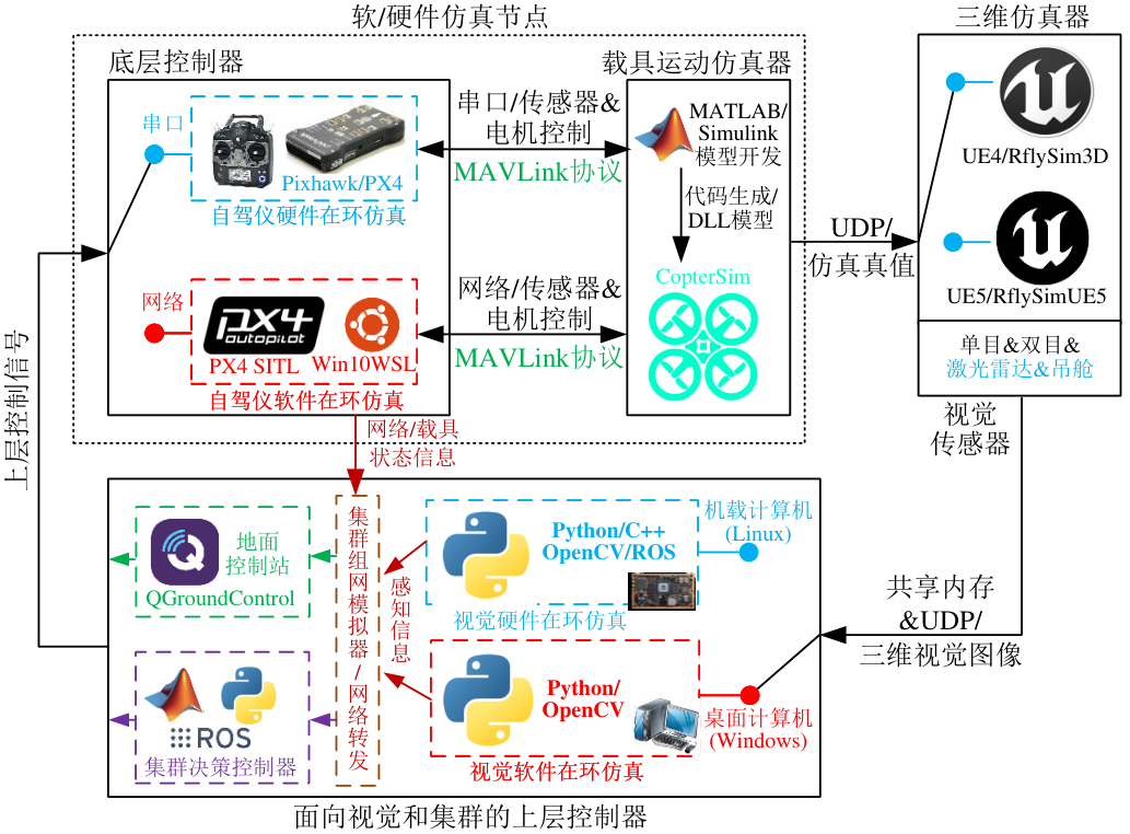
Four Major Functional Modules
| Module | Role | Implementation Highlights |
|---|---|---|
| Vehicle Motion Simulator | Simulates real physical environment responses (kinematics, sensors, actuator modeling) | Builds 6-DOF models based on MATLAB/Simulink → Auto-generates C/C++ → Compiles to DLL → Loaded into CopterSim for periodic solving; can flexibly embed fault models for fault injection |
| Low-Level Controller | Receives sensor data, generates control commands, drives the simulated vehicle for stable operation | Default uses the open-source PX4 autopilot; supports SITL (software), HITL (hardware), and FPGA high-fidelity in-the-loop modes |
| 3D Simulator | 3D visualization, collision detection, communication reachability assessment, large scene support, visual sensor data generation | RflySim3D (UE4, primary) and RflySimUE5 (UE5, full version) |
| High-Level Controller | Coordinates the "Perception-Decision-Execution" control chain, targeting vision and swarm control | Composed of multi-modal perception decision layer, networking communication layer, and swarm control layer; inputs multi-modal sensor data from the 3D simulator and state estimates from the low-level controller, outputs external control commands |
Closed-Loop Data Flow
The "Low-Level Controller" communicates bidirectionally with the "Vehicle Motion Simulator" via network interfaces (SITL) or USB serial ports (HITL): ① Replaces sensor input – receives virtual sensor data and shields the original sensor chips; ② Replaces actuator output – disables real motor ports and sends control quantities (e.g., PWM) back to the simulator's actuator model to drive the virtual vehicle's motion. This connects the entire control system into a closed loop, avoiding manual modeling of complex embedded control logic.
Simulation Modes
RflySim provides two levels of in-the-loop simulation and extends an FPGA high-fidelity mode for third-party closed-source autopilots.
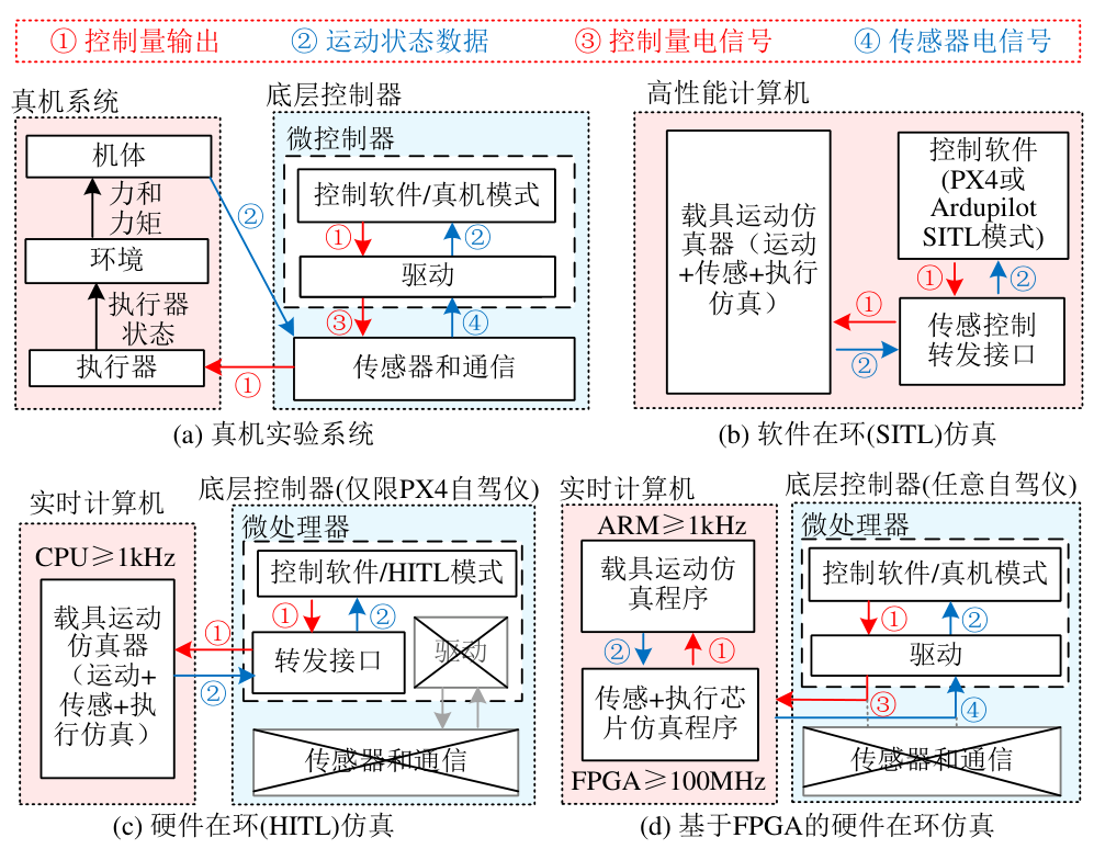
SITL vs. HITL Comparison
| Comparison Item | SITL (Software-in-the-Loop) | HITL (Hardware-in-the-Loop) |
|---|---|---|
| Autopilot Form | PX4 software runs locally (WSL/Ubuntu or Docker) | PX4 deployed on physical autopilot hardware (e.g., Pixhawk 6X) |
| Communication Link | TCP/UDP network interface | USB serial port (or network interface) |
| Hardware Requirement | No additional hardware needed, low cost | Requires a real autopilot |
| Real-time Performance/Fidelity | Slightly lower (lacks real signal noise and latency) | High, close to real hardware |
| Applicable Stage | Prototype design, rapid algorithm iteration (most readers) | Deployment verification, software-hardware integration testing (advanced readers) |
Same Control Logic
SITL and HITL run the same PX4 control logic, ensuring consistent algorithm behavior. It is recommended to use SITL for rapid iteration initially, then switch to HITL for stability verification and real-hardware adaptation upon maturity.
FPGA High-Fidelity Simulation Mode
To address issues where third-party closed-source autopilots are not plug-and-play, and dedicated simulation modes consume computing power and interfere with real hardware behavior, RflySim introduces a FPGA-based hardware-in-the-loop mode:
- Physically Shield Sensor Hardware – Remove IMU, GNSS, and other modules from the autopilot, shielding native sensor inputs without modifying the firmware;
- Introduce FPGA Middle Layer – A real-time simulation system simulates low-level protocols like SPI, I²C, UART, PWM between the controller and simulator, reproducing real perception inputs at the signal level;
- Maintain Real Hardware Operation Mode – The autopilot always connects to the closed loop in its real state, supporting sensor chip-level fault injection;
- High Universality – Only requires knowledge of the sensor/actuator chip models and communication verification logic used by the autopilot for black-box access. The prevalence of low-cost "ARM + FPGA" hybrid platforms (e.g., Xilinx ZYNQ) makes this solution increasingly cost-effective.
Onboard System-in-the-Loop and Distributed Swarm Simulation
- Onboard System Software-in-the-Loop: Perception and decision algorithms run locally (Python/WSL/ROS), with images/point clouds interacting with the simulator via shared memory or UDP at high speed, suitable for algorithm design and prototype verification.
- Onboard System Hardware-in-the-Loop: The simulator transmits images over a local area network to a real onboard platform (Ubuntu + ROS) for running vision algorithms, forming a complete "Perception-Decision-Execution" closed loop. This is a crucial intermediate step from simulation to real-world deployment.
- Distributed Swarm Simulation: Supports running "3D Simulator / Vehicle Motion Simulator / Low-Level Controller / High-Level Controller" in parallel on multiple hosts. The number of nodes and communication topology can be scaled as needed to address computational bottlenecks in multi-vehicle vision and point cloud processing. See
DistSim.batand Distributed Simulation SDK for details.
Component Overview
RflySim integrates various general-purpose development tools and custom software interfaces, categorized into the following seven types based on their roles.
Core Simulation and Development Platforms
| Component | Role |
|---|---|
| MATLAB/Simulink | Core for modeling and control algorithm design. Drag-and-drop graphical construction of unmanned system models and control algorithms, interfacing with RflySim interface modules for automatic code generation, firmware compilation/upload, and offline/online co-simulation |
| Unreal Engine (UE) | Supports high-fidelity 3D simulation and visual perception environments. RflySim's self-developed visualization platform RflySim3D (based on UE4/UE5) supports custom scene import, high-fidelity rendering, and visual sensor data generation |
Operating Systems and Development Environments
| Component | Role |
|---|---|
| Windows | Primary simulation platform with a user-friendly GUI, running RflySim3D, Simulink, and configuration tools |
| Ubuntu | Standard platform for unmanned system algorithm development and deployment (20.04/22.04 LTS), integrating ROS 1/2, PX4 SDK, OpenCV, TensorFlow, compatible with embedded platforms like Jetson Orin NX, RK3588 |
| WSL | Cross-platform bridging environment, includes the WinWSL compilation environment (WSL 1/2 + Ubuntu 20.04/22.04), pre-installed with PX4, ArduPilot compilation toolchains and robotics development frameworks, supports WSL2 GPU acceleration |
| Docker | Containerized deployment and cross-architecture image generation, integrated within WSL2; combined with QEMU/Buildx, can directly generate ARM64 onboard algorithm images on an X86 host |
Programming Languages and Core Libraries
| Component | Role |
|---|---|
| C/C++ | Core language for low-level control development and ROS algorithm deployment, used for autopilot firmware (PX4, ArduPilot) and high real-time nodes |
| Python | Powerful tool for high-level algorithm development and data processing, used for visual perception, path planning, target recognition, and strategic decision-making, combined with OpenCV, NumPy, TensorFlow, PyTorch |
| OpenCV | Core library for computer vision algorithm development, integrated in both Windows/Python and WSL/Ubuntu/C++/Python environments, providing examples for static recognition, dynamic tracking, localization estimation, etc. |
Middleware and Communication Protocols
| Component | Role |
|---|---|
| ROS 1/2 | Middleware for unmanned system perception and communication. ROS 1, centered around topics/services/parameter server, is suitable for teaching and prototyping; ROS 2, based on DDS, offers stronger real-time performance, security, and distributed support. The toolchain provides one-click switching scripts (Ros2ComMode.bat) |
| IPC (Inter-Process Communication) | Data transfer mechanisms for multi-process collaboration. Shared memory is used for zero-copy high-speed topic transmission; Sockets (TCP/UDP) – TCP ensures reliability for control commands, UDP provides low latency for image/sensor data. Communication between CopterSim, ground stations, Python/Simulink control programs, and RflySim3D is all implemented via UDP |
See Toolchain Protocol Summary for details.
Autopilot Software and Hardware Ecosystem
| Component | Role |
|---|---|
| PX4 | Core software for open-source autopilot control systems, modular, highly real-time, supports multi-rotor/fixed-wing/VTOL/UGV, etc.; natively integrates SITL/HITL simulation modes and MAVLink forwarding |
| Pixhawk | Open-source autopilot hardware platform, compatible with PX4 and ArduPilot; default platform for HITL and real-world experiments (e.g., Pixhawk 6X) |
| QGroundControl | Cross-platform ground station, providing mission planning, real-time monitoring, parameter tuning, log management, connects to PX4/ArduPilot via MAVLink |
| MAVLink | Lightweight bidirectional communication protocol standard, runs through the entire "Simulation-Deployment-Experiment" process. High-level adaptation libraries: MAVROS (ROS), Pymavlink (Python), MAVSDK (C++/Python) |
Onboard Computers and External Control
| Component | Role |
|---|---|
| Onboard Computer | The "brain" of the unmanned system, running intelligent perception, path planning, and control computations. Recommended: NVIDIA Jetson Orin NX (Ampere GPU + 8-core ARM CPU, Super version up to 157 TOPS), can run the same Ubuntu + ROS/OpenCV environment as WSL, and leverage Docker for cross-platform image distribution |
| Offboard Mode | External control mechanism, allowing external computing units to send real-time control commands (velocity/position/attitude/waypoint) to the autopilot via MAVLink. In RflySim, this is achieved through the "ROS + MAVROS + PX4" linkage for closed-loop control |
Automation and Interface Tools
| Component | Role |
|---|---|
| BAT (Batch Files) | One-click startup and task scheduling automation. Provides numerous custom scripts for automating simulation startup, WSL initialization, algorithm deployment, and data recording. See BAT Script Quick Reference |
| CMD (Command Prompt) | Entry point for simulation control and interaction, usually automatically popped up by BAT scripts, used for inputting parameters like vehicle count/initial position/startup mode, and can quickly terminate background simulation processes |
| DLL (Dynamic Link Library) | Modular model and algorithm interface. Loading different DLLs allows quick switching of simulated vehicle dynamics characteristics without recompiling the main program. The hot-swappable nature facilitates model iteration and supports closed-source algorithm packaging |
RflySim Self-Developed Core Software
The toolchain is primarily composed of the following self-developed core software, interfaces, and examples (more details can be found in the installation directory RflySimAPIs\2.RflySimUsage\0.ApiExps\e1_RflySimSoftwareReadme):
| Software | Description | Detailed Documentation |
|---|---|---|
| CopterSim | Core simulation software, integrating model configuration, communication relay, UI settings, and autopilot simulation connection, responsible for dynamics model loading and closed-loop control simulation | — |
| RflySim3D / RflySimUE5 | 3D simulators based on UE4/UE5, handling visualization, collision detection, visual sensor data generation, etc. | 3D Resource Index, Shortcut Keys & Console Commands, Model Import XML |
| BAT One-Click Scripts | Collection of automation scripts for simulation startup and environment configuration | BAT Script Quick Reference |
| RflySimAPIs | Python/Simulink/ROS development interfaces and example system, covering control, communication, vision, swarm, PHM, etc. | Python SDK, Simulink Toolbox, ROS/ROS2 Interface |
Vision Related
For visual sensor configuration and communication protocols, see Visual Sensor Configuration Protocol and Vision-Related Communication Protocols; for automated testing, see Automated Test Configuration Protocol.