The RflySim Toolchain is a highly reliable development, testing, and evaluation platform specifically designed for unmanned control system development, large-scale swarm coordination, AI-based vision, and other cutting-edge research fields. Built on a Model-Based Design (MBD) philosophy, the toolchain leverages Pixhawk/PX4, MATLAB/Simulink, Python/AI, Linux/ROS, and other development tools, covering 3D scene modeling, vehicle motion modeling, low-level flight control, intelligent perception and planning, health assessment and fault diagnosis, swarm game-theoretic decision-making, and more. Following the MBD workflow — unmanned system modeling → graphical modular controller design → automatic code generation → software-in-the-loop (SIL) simulation → hardware-in-the-loop (HIL) simulation → rapid real-aircraft deployment — the toolchain enables a fast transition from simulation to real flight. The intelligent unmanned swarm system curriculum is divided into 10 chapters, organized progressively from foundational to advanced topics, guiding users step by step to develop their own intelligent unmanned swarm systems. The chapter relationships are shown below:
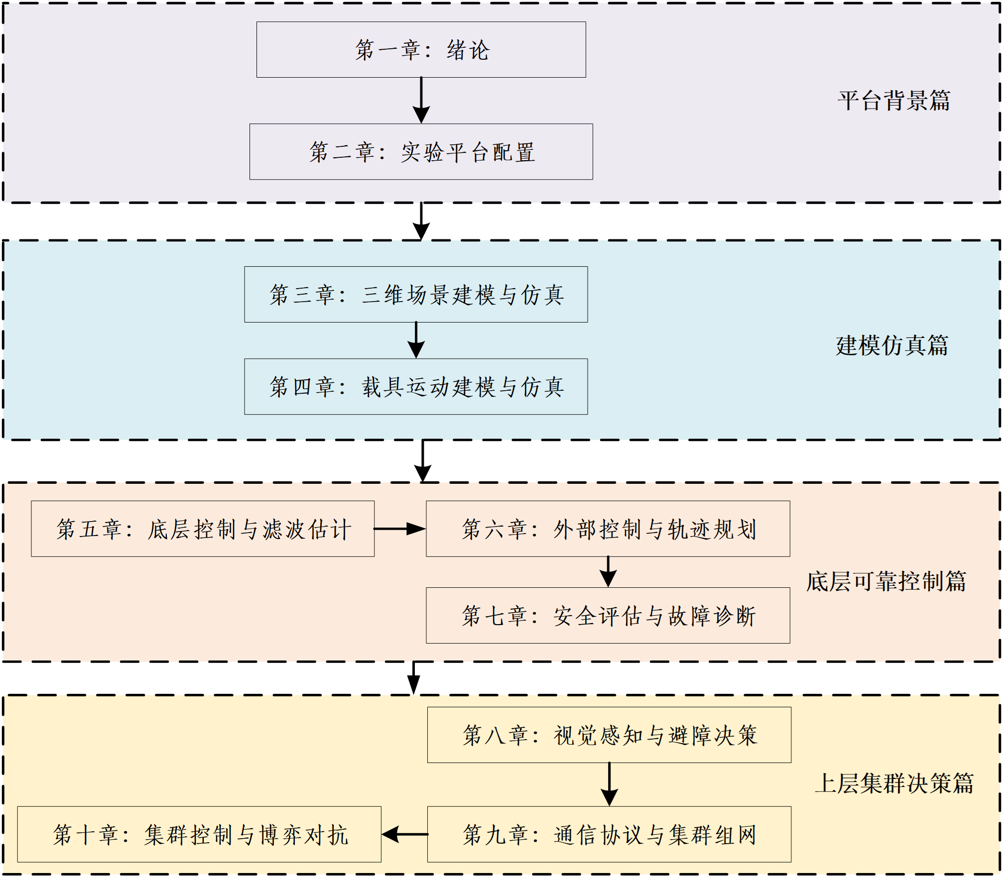
Chapter 1: Introduction
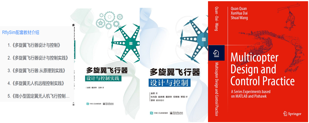
This chapter covers the foundational knowledge of the toolchain, supporting textbooks, and software/hardware overview. For details, see: Chapter 1 — Toolchain Installation and Learning Methods
Chapter 2: Experimental Platform Configuration
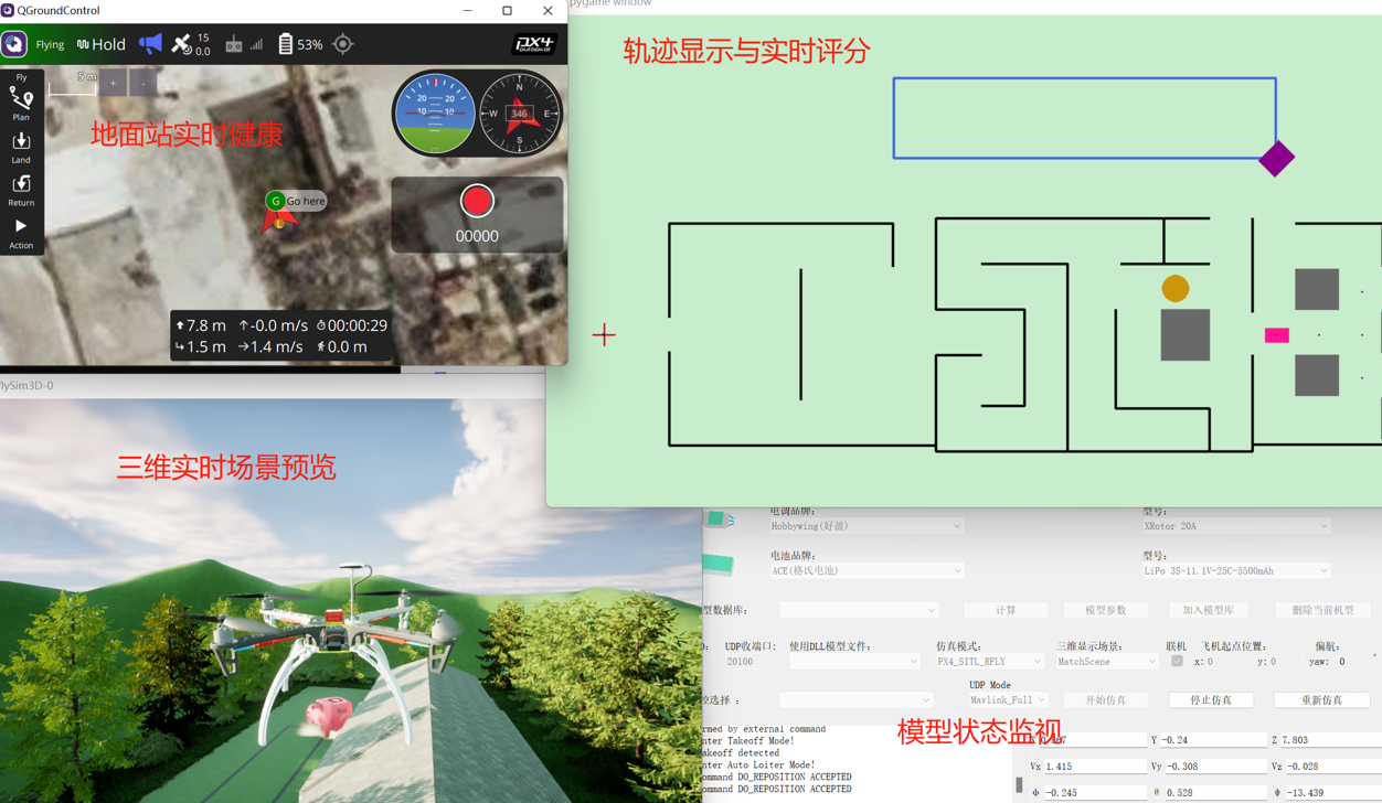
This chapter covers toolchain module introduction, UI description, key interface explanation, overall experimental workflow, and troubleshooting. For details, see: Chapter 2 — Experimental Platform Configuration and Usage
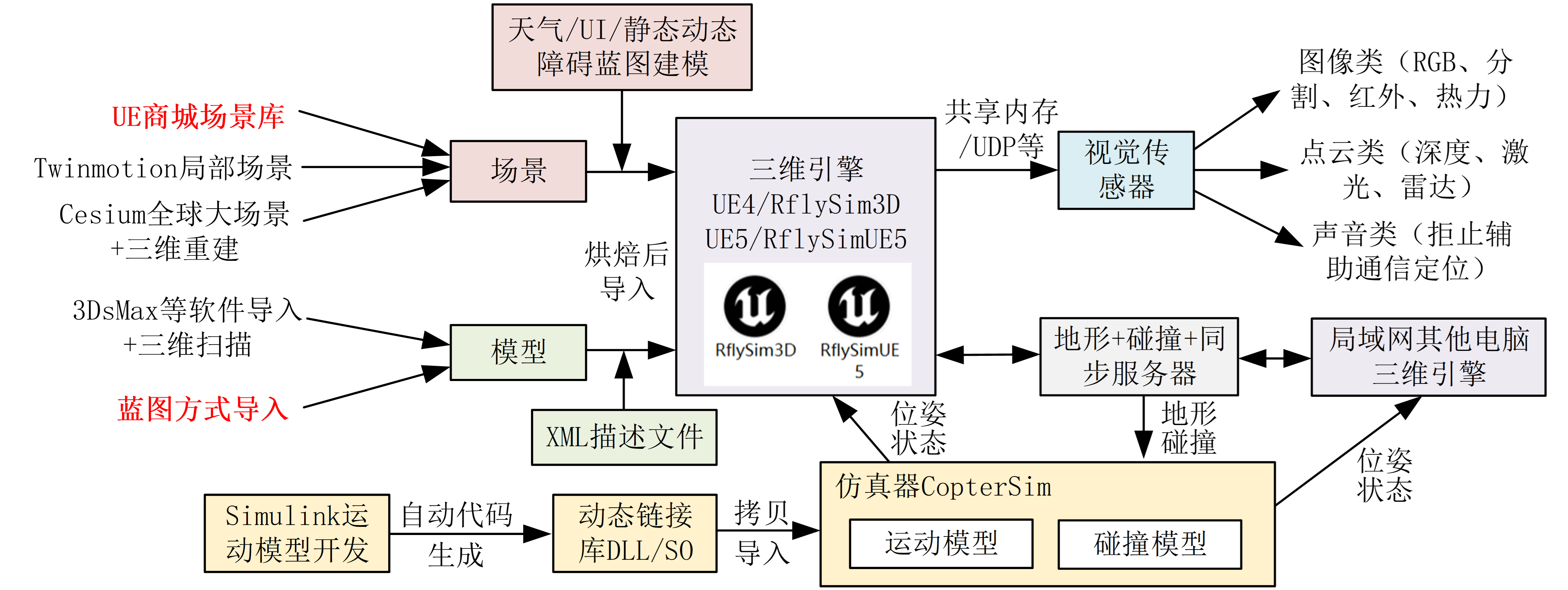
Chapter 3: 3D Scene Modeling and Simulation
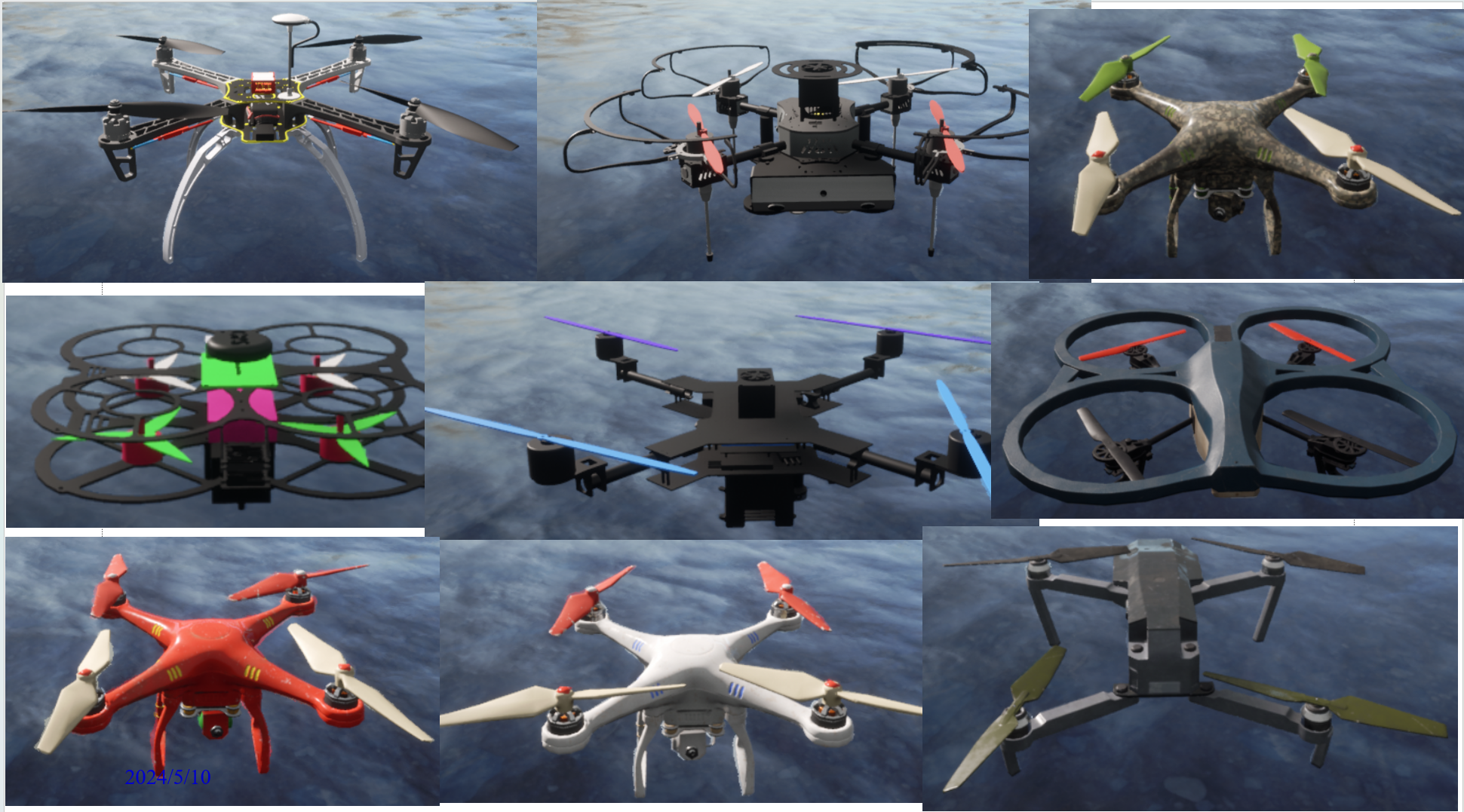
This chapter covers 3D scene modeling with support for custom development, rapid customization and import of aircraft and scenes, externalized collision models for reduced engine load, and a distributed architecture for large-scale swarm simulation. For details, see: Chapter 3 — 3D Scene Modeling and Simulation

Task (Competition) Performance Evaluation (Scoring)
Various Special Effects Production
VR Virtual Reality
Infrared Electro-Optical Pod
360° LiDAR Point Cloud Sensor Simulation
Chapter 4: Vehicle Motion Modeling and Simulation
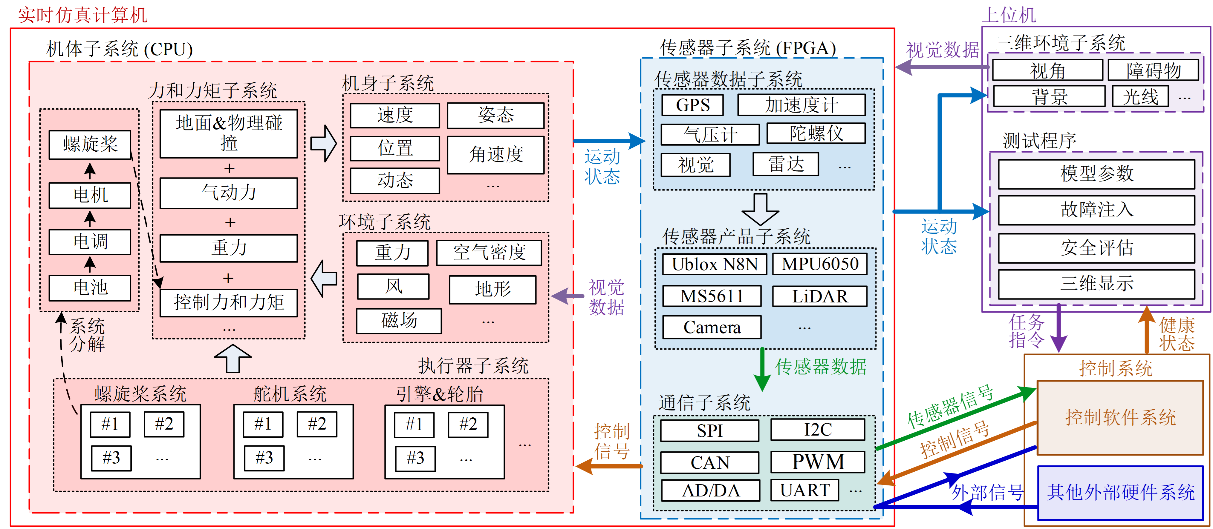
In this chapter, within the given Simulink input/output interface framework, users can rapidly implement various vehicle models combined with the platform's identification and evaluation tools, optimize and evaluate model accuracy, and use automatic code generation to convert models into dynamic link libraries (DLLs) for import alongside PX4's native controller or a custom Simulink controller for HIL simulation. For details, see: Chapter 4 — Vehicle Motion Modeling and Simulation
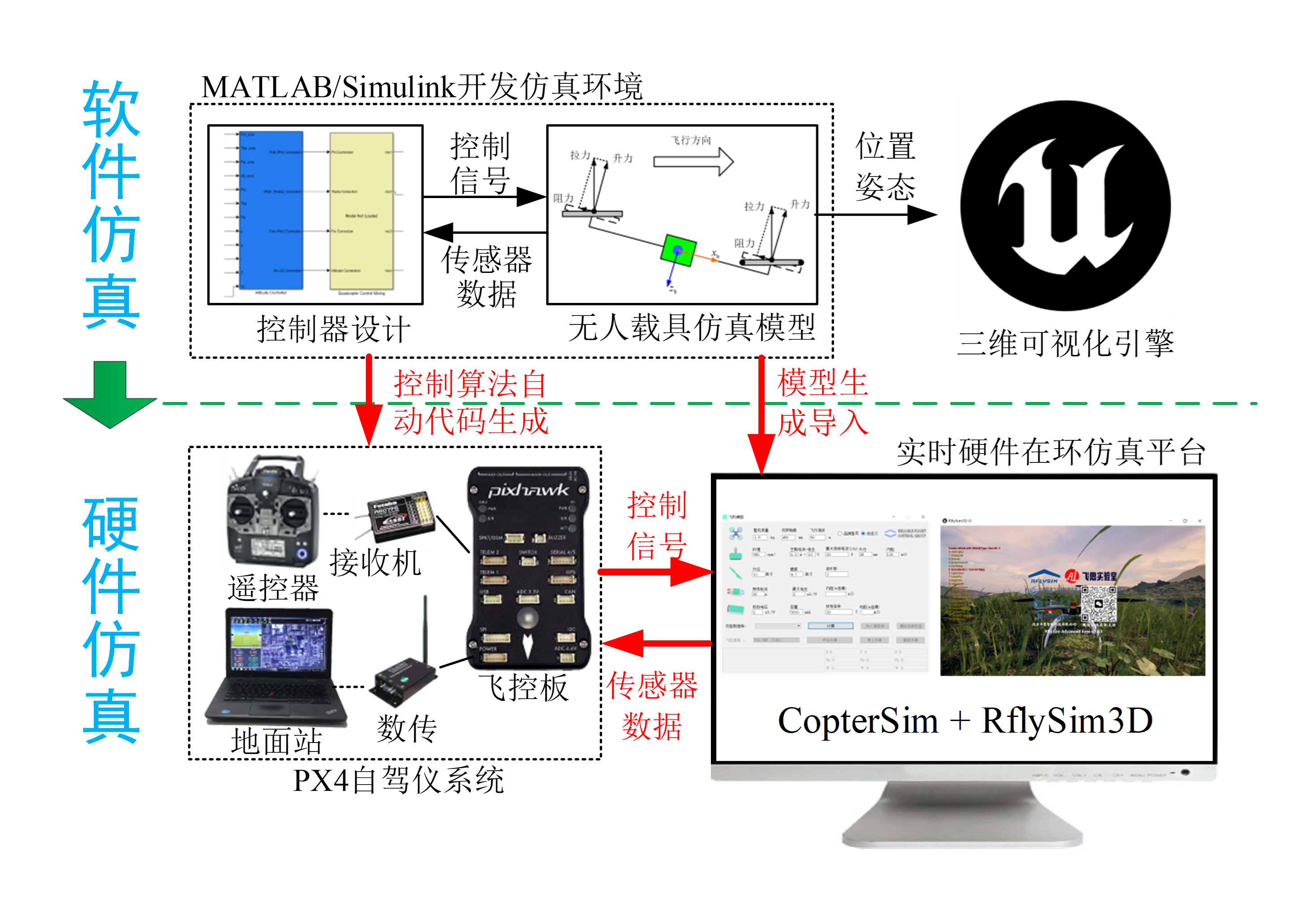
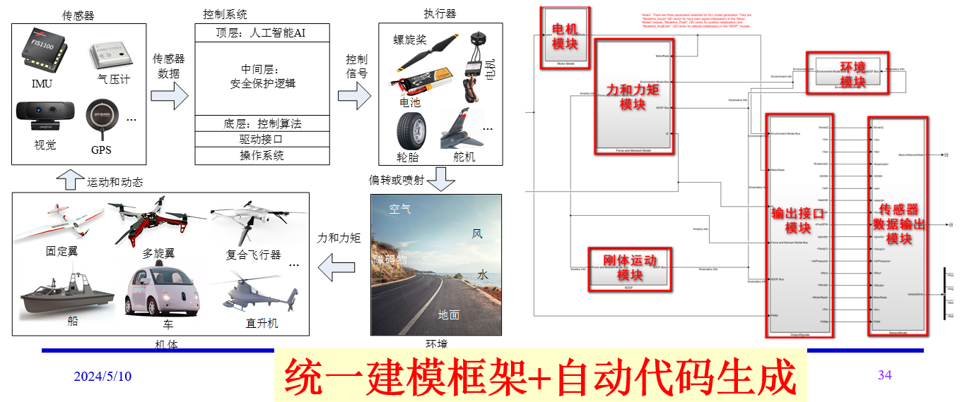 Using a standardized modeling framework implemented in graphical modular simulation tools such as Simulink, the simulation system is obtained via code generation.
Precise Modeling: Bifilar Pendulum Moment of Inertia Measurement
Propulsion System Test Bench: Motor-Propeller Response Curves
Custom Wind Tunnel for Incoming Flow Model Measurement
Frequency Sweep + Real Flight Frequency/Time Domain Model Validation
Multirotor Precise Modeling + Fault Injection
Tilt-Rotor Hardware-in-the-Loop Simulation
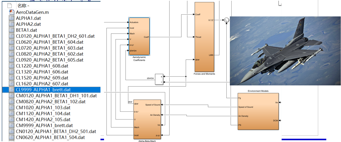
Fixed-Wing Model (F16 Example): Full-Envelope Aerodynamic Coefficient Import
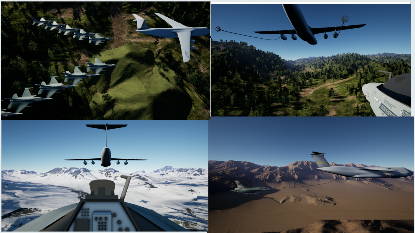
F16 Aerial Docking Algorithm Training Platform
Helicopter Simulation
Helicopter Real Flight Experiment
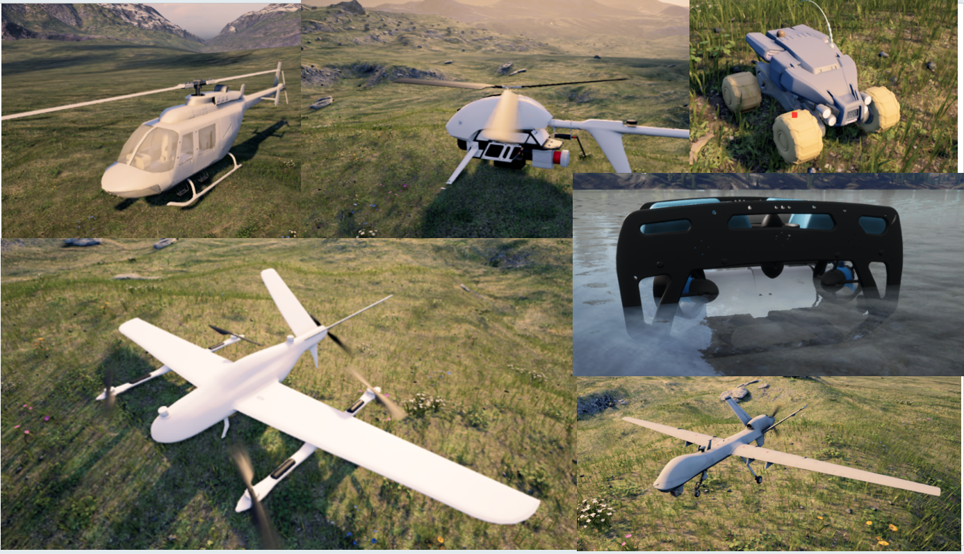
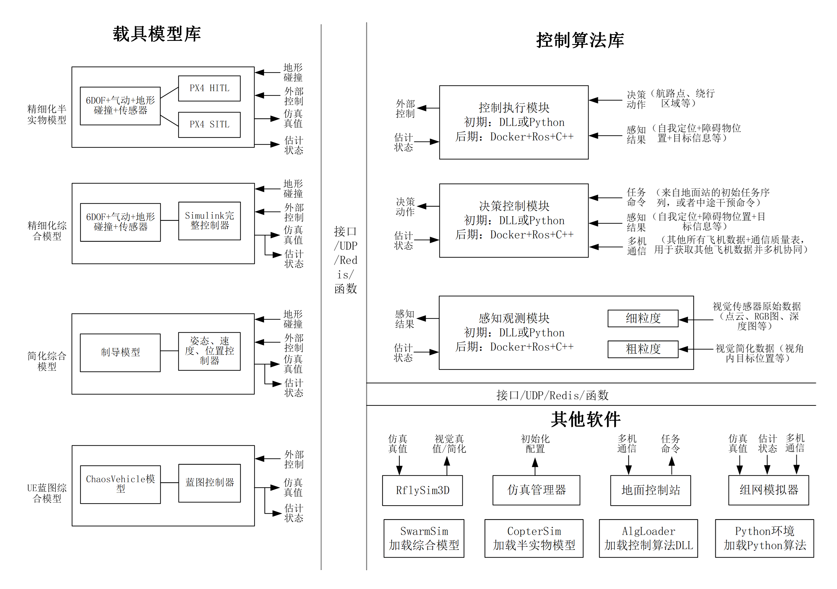
The models are divided into four types, all supporting DLL-based invocation from Python/Simulink/C++ for large-scale swarm and AI training scenarios:
- Detailed 6-DOF model + autopilot hardware-in-the-loop simulation
- Detailed 6-DOF model + Simulink controller integration → detailed comprehensive model
- Guidance-level simplified model + Simulink controller integration → simplified comprehensive model
- UE physics engine + Blueprint controller integration → UE Blueprint comprehensive model (better terrain and collision response)
- Models developed on this platform also support DLL generation for invocation by Python and other programs, accelerating AI control training including deep reinforcement learning and large-model decision-making and game-theoretic scenarios.
VTOL UAV Simulation
VTOL UAV Real Flight
Tailsitter VTOL Simulation
Tailsitter VTOL Real Flight
Unmanned Ground Vehicle Simulation
Unmanned Surface Vessel Simulation
Underwater Vehicle HIL Simulation and Underwater Visual SLAM Verification
ZV15E VTOL UAV Real Flight Video
ZV15E VTOL UAV Assembly Video
ZV15E VTOL UAV Follow-Cam Video
ZV15E VTOL UAV Snow Flight Video
ZV15E VTOL UAV Gimbal Vehicle-Tracking Video
Chapter 5: Low-Level Control and Filtering Estimation
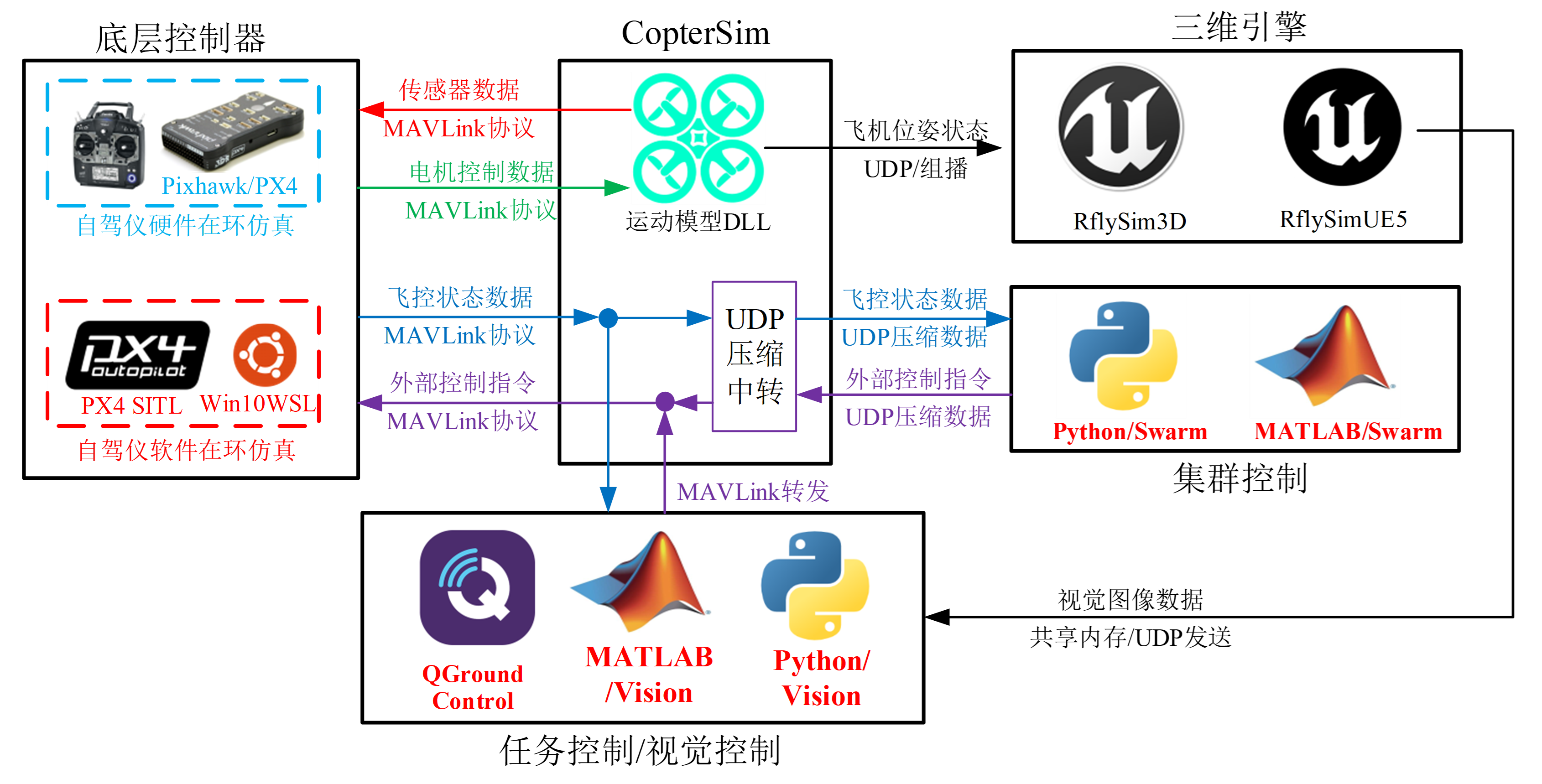
Model-based low-level flight control design: Given control requirements, how can you rapidly deploy control algorithms on real aircraft? Simply design the controller in Simulink, then proceed through SIL simulation → automatic code generation → HIL simulation → indoor testing → outdoor real flight to quickly verify and deploy algorithms. For students, this greatly lowers the barrier to learning UAV control; for engineers, it significantly improves algorithm development efficiency.
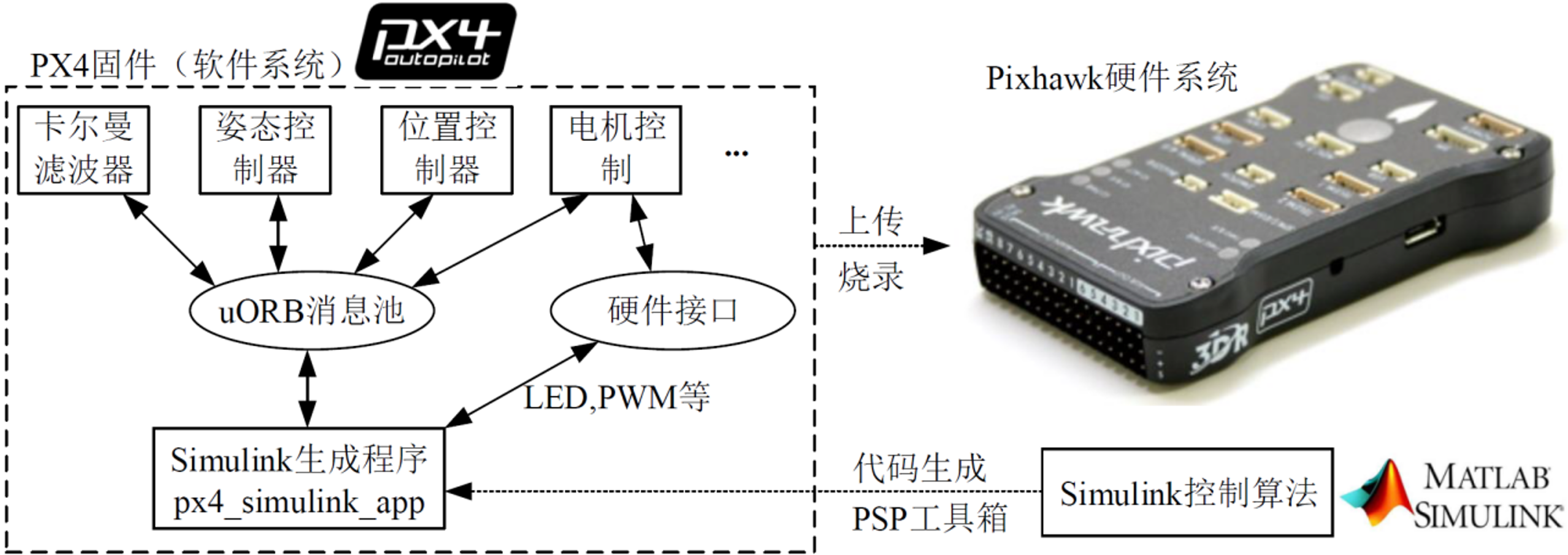
Simulink controller development + automatic code generation eliminates the need for C/C++ low-level development. Through the uORB message pool, a ROS-like publish/subscribe mechanism is achieved, enabling more flexible algorithm integration. For details, see: Chapter 5 — Filtering Estimation and Low-Level Control
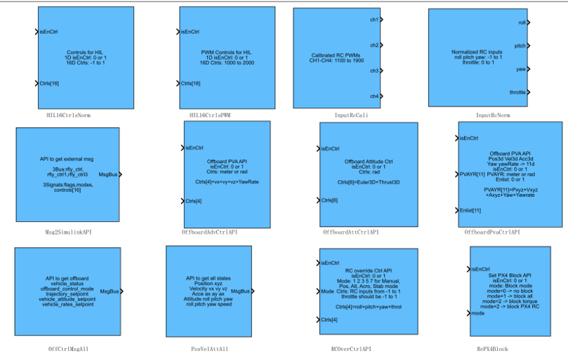
A new low-level development interface (released with RflySim v3.03):
- Supports control input at any layer: motor, force+torque, angular velocity, attitude, acceleration, velocity, position, or RC layer;
- Supports switching between PX4's native controller and custom Simulink controllers during flight;
- More convenient support for HIL simulation and experiments across various vehicle types;
- More convenient support for upper-level information input (waypoints, trajectories, etc.).
Note: The v3.02 version only supports motor-layer input and does not allow switching back to the PX4 controller at any time, making algorithm development and experimentation more difficult. The new interface resolves this issue.
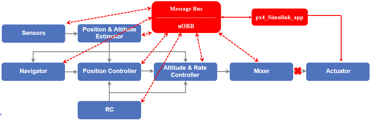
- PX4 uses a uORB publish/subscribe message mechanism, allowing any APP to acquire and publish data from the uORB message pool.
- Simulink-generated code deploys to Pixhawk as an APP called px4_simulink_app, which communicates with other APPs through the uORB message pool system.
- System identification → precise mathematical model → modern control theory (LQR, ADRC, MPC, MCC, etc.) → automatic code generation → direct autopilot deployment. V.S. PX4 native PID after extensive parameter tuning.
- Simulink replaces only the attitude loop while retaining all other loops; position-hold hover test under fan disturbance.
Conclusion: Precise model + modern control theory + RflySim automatic code generation enables rapid controller parameter calculation (no repetitive tuning needed) and offers superior disturbance rejection (higher stability margins).
FeiSi X150 Aircraft Bench Experiment
Recommended teaching aid: FeiSi X150 aircraft, 150mm wheelbase (180g weight), compact and safe, stable indoor hover with optical flow, compatible with GPS outdoor tests + motion capture indoor experiments.
Combined with a high-precision identified model + custom desktop test bench, rapid UAV algorithm development and verification can be achieved.
Quadrotor Three-Motor Failure Degraded Control
Based on modern fault-tolerant control theory, the RflySim Toolchain achieves controlled emergency landing of a quadrotor with one, two, or three motor failures. Precise modeling → model-based control → automatic code generation → HIL simulation → real aircraft experiment — facilitating rapid development of novel algorithms.
Chapter 6: External Control and Trajectory Planning
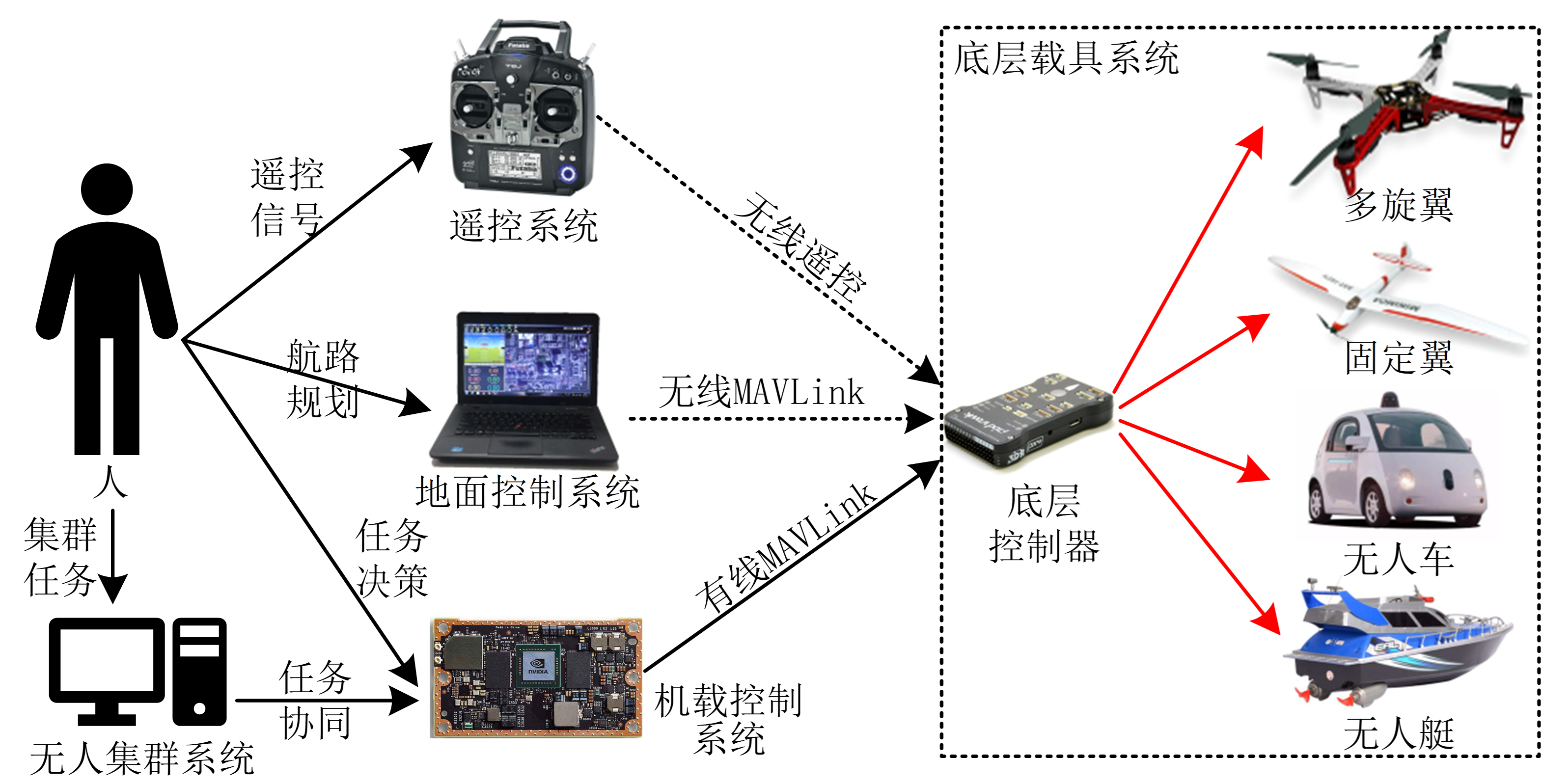
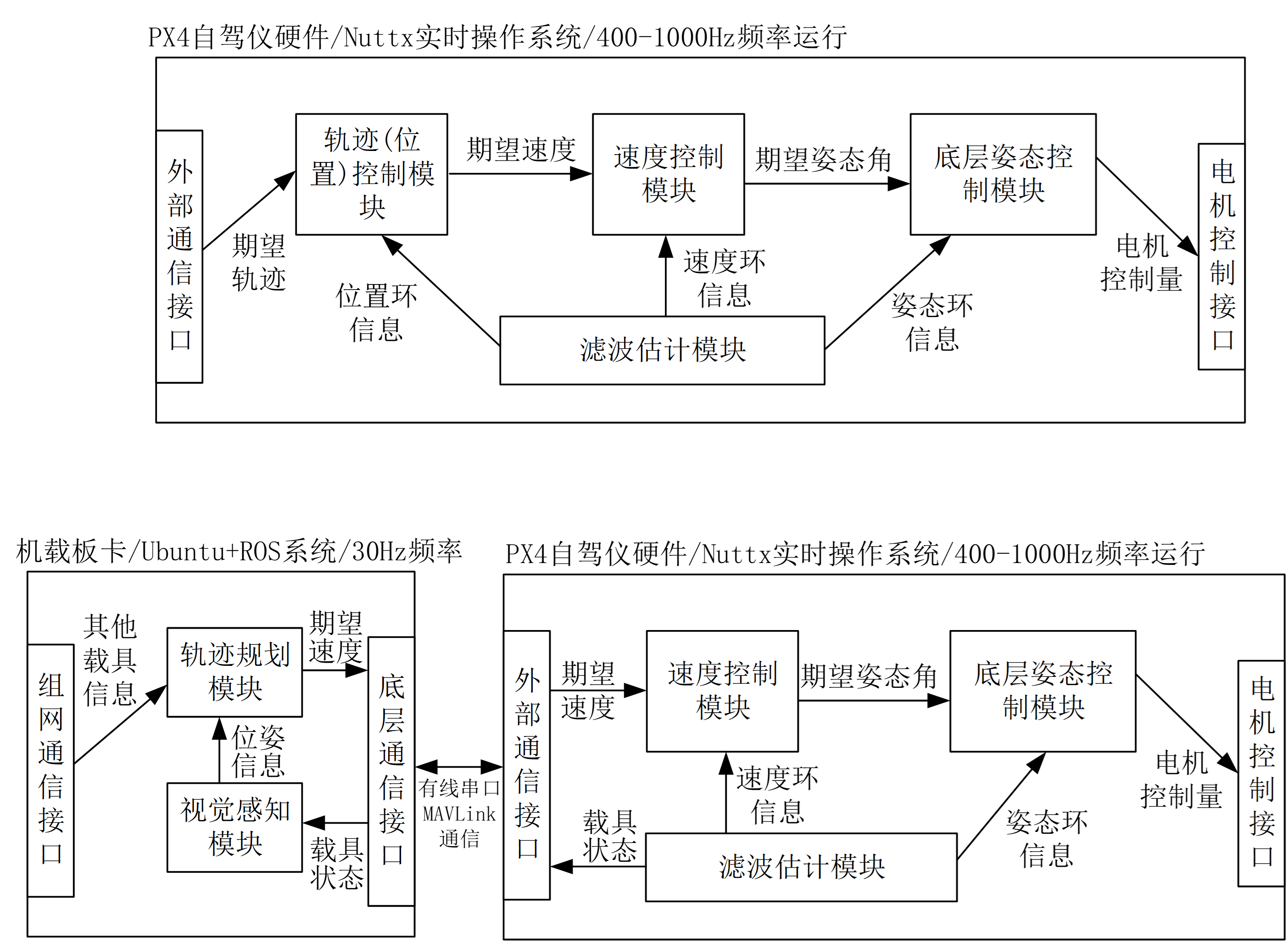
Modern flight control architecture: The low-level autopilot retains only attitude or velocity loop control to ensure basic reliable flight. All higher-level planning and control logic resides on the onboard companion computer and is relayed to the autopilot via external control interfaces. The low-level autopilot targets a specific airframe and is rapidly implemented using system identification + modern control methods + automatic code generation. Open-source autopilots like PX4, designed to be compatible with various airframe sizes and vehicle types, contain significant redundancy that may not suit UAV manufacturers or research institutions. For details, see: Chapter 6 — External Control and Trajectory Planning
Internal/external control is relative:
- The trajectory planning model used in external control can also run inside the autopilot.
- Similarly, much of the internal autopilot logic can be moved to the companion computer.
- For highly maneuverable control tasks, algorithms can run inside the autopilot at higher frequencies.
- Examples include high-maneuverability trajectory following, through-window flight, inverted flight, and other acrobatic maneuvers, as well as AI algorithm training for such tasks.
Interface tutorials: RC control, MAVLink communication, pymavlink, MAVSDK, MAVROS, ROS1/2. Algorithm development examples: Simulink UAV algorithm library for upper-level development, trajectory generation, obstacle avoidance planning, AI training, and more.
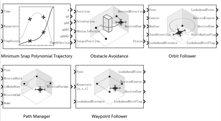
For low-level control algorithms: MATLAB/Simulink's rich control and planning libraries + AI training libraries are recommended for rapid algorithm development and verification, with automatic code generation for fast deployment.
Note: The RflySim Toolchain also plans to add compatibility with the domestic MWORKS platform in the future.
Air-Ground Cooperative External Trajectory Planning Control
Chapter 7: Safety Assessment and Fault Diagnosis
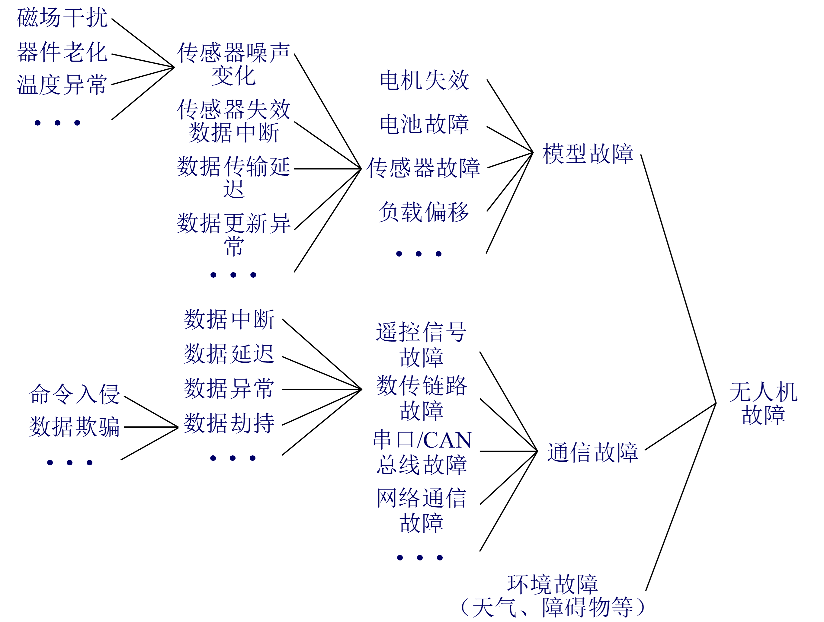
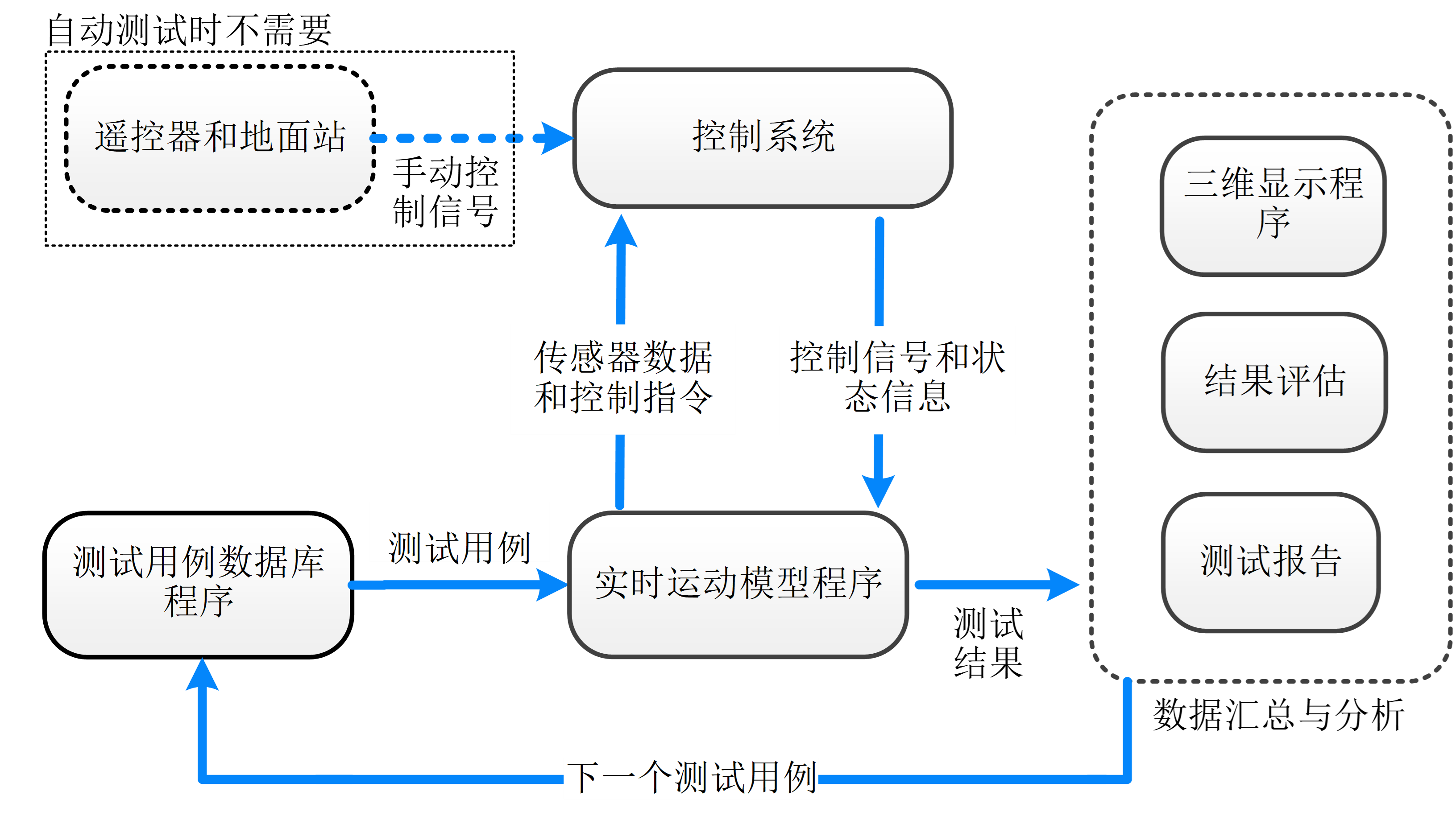
Beyond basic functional testing, safety and reliability testing of UAVs under failure conditions is also critical. This system categorizes faults into three types: model faults (related to aircraft mathematical models), communication faults (related to data transmission), and environmental faults (related to 3D scenes). For details, see: Chapter 7 — Health Management and Safety Assessment
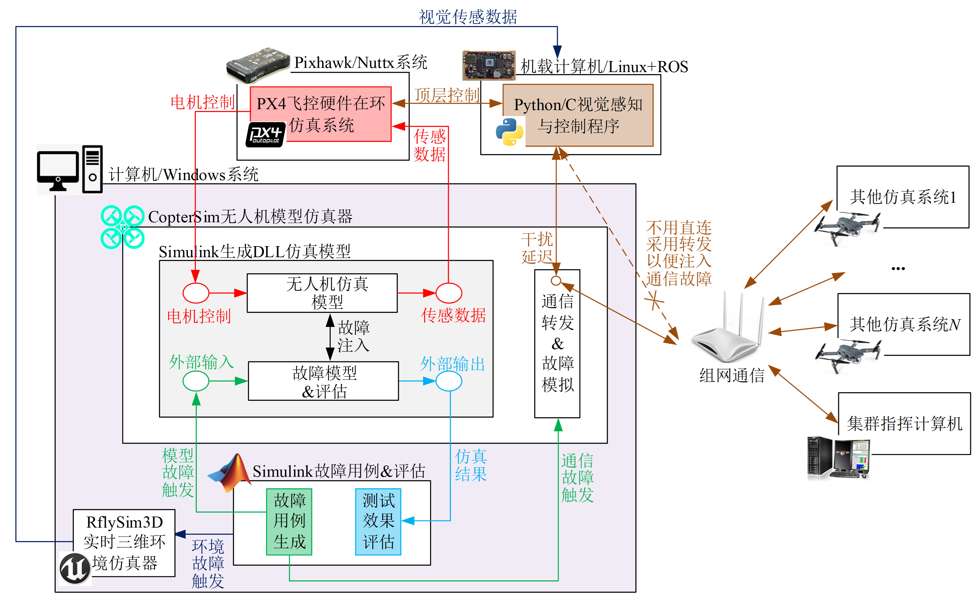
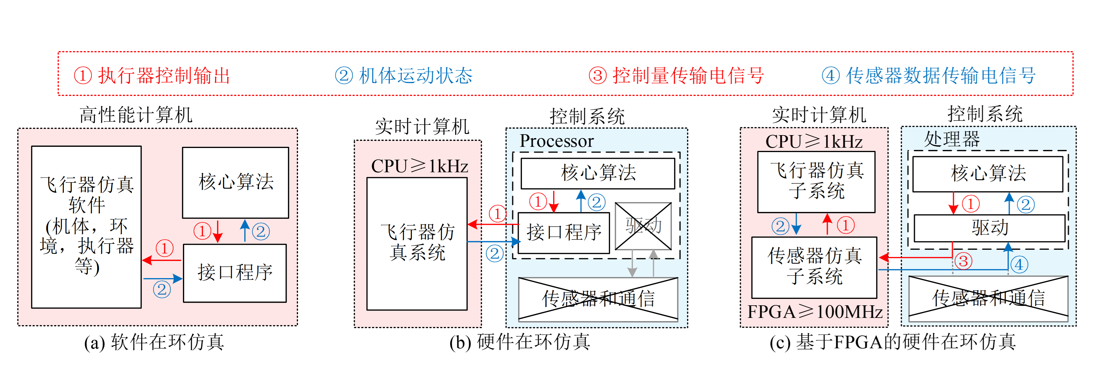
From motion dynamics simulation → sensor data simulation → sensor chip simulation;
from pure algorithm software testing → full system software/hardware testing.
Fault Injection Experiment
Fault Injection and Diagnosis Algorithm Verification
Chapter 8: Multimodal Perception and Intelligent Decision-Making
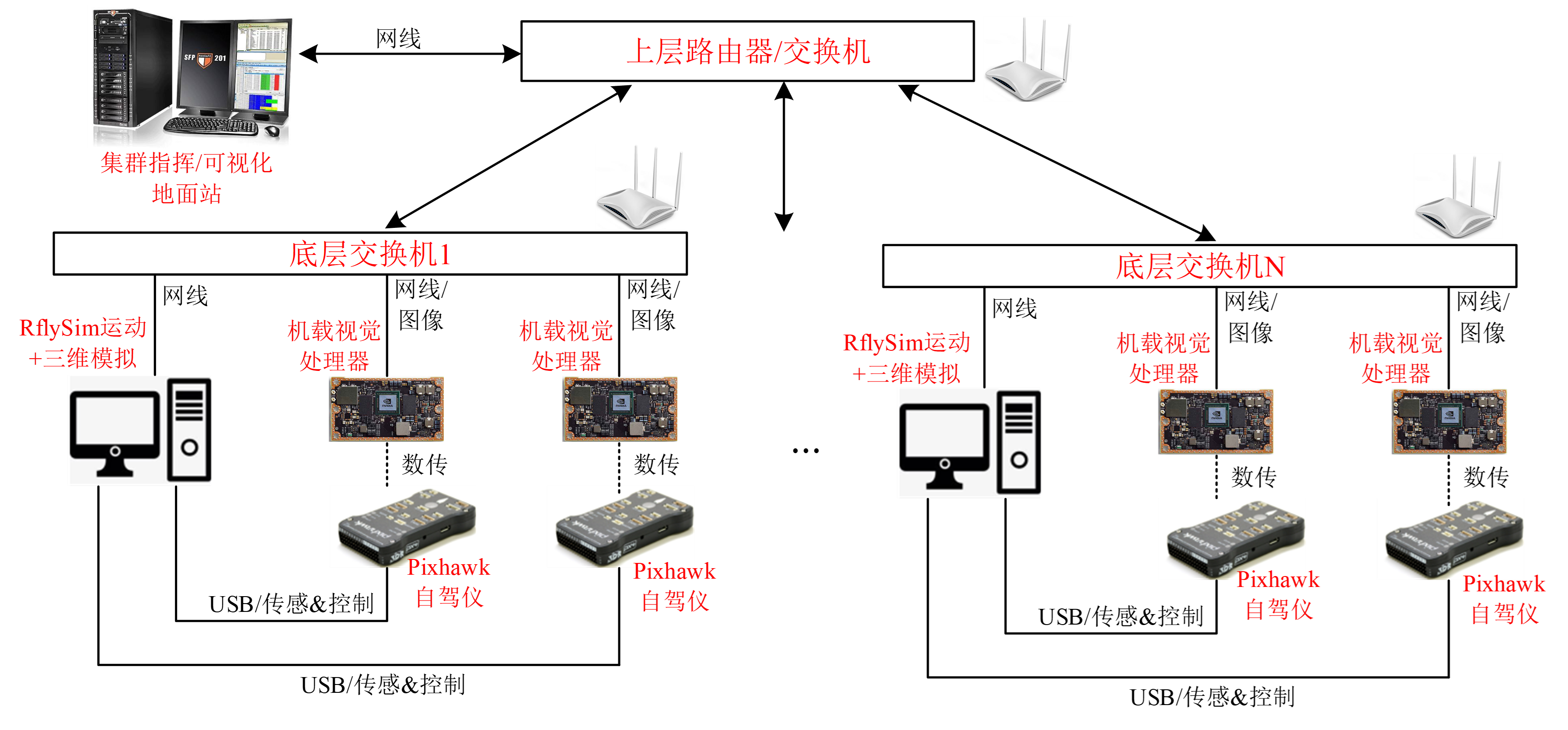
Leveraging the RflySim Toolchain's distributed architecture, external model support, semi-physical simulation, and multi-vehicle synchronization capabilities, users can develop distributed architectures for independent multi-vehicle visual HIL verification, visual SLAM semi-physical simulation, and rapid real-aircraft algorithm migration. For details, see: Chapter 8 — Multimodal Perception and Intelligent Decision-Making
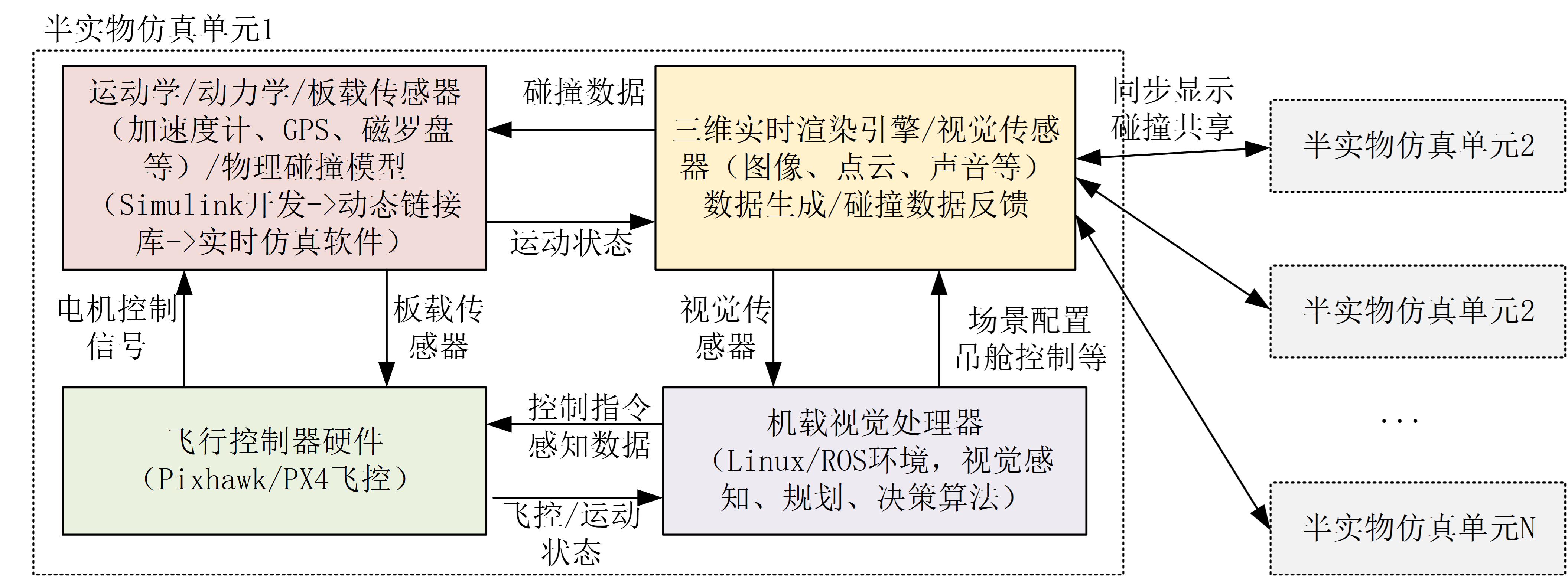
5-Vehicle Vision-Shared SLAM Semi-Physical Simulation
Simulation Algorithm Development and Verification
Rapid Real-Aircraft Algorithm Migration
3D Mapping in GPS-Denied Environments
High-Speed Visual Strike Experiment
LLM-Controlled UAV: Responding to Voice Command — "Fly Upstairs and Check if the Bathroom Window Is Closed"
Chapter 9: Multi-Vehicle Communication and Intelligent Networking
In this chapter, all aircraft data is first sent to a network simulator, which then forwards data to subscribed vehicles based on actual conditions. Network simulation is divided into coarse-grained simulation (primarily modeling upper-layer characteristics such as delay and packet loss) for communication quality evaluation, and fine-grained NS3-based networking simulation that supports lower-layer networking algorithm development and verification. For details, see: Chapter 9 — Multi-Vehicle Communication and Intelligent Networking
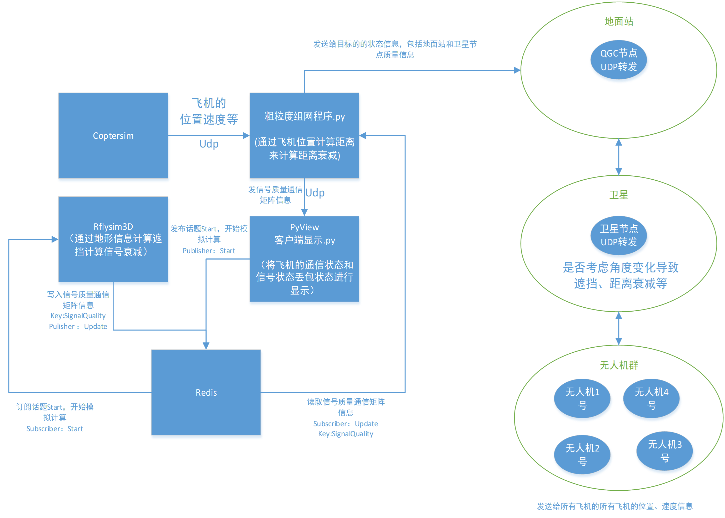
Swarm Communication Quality Simulation
Chapter 10: Swarm Coordination and Game-Theoretic Confrontation
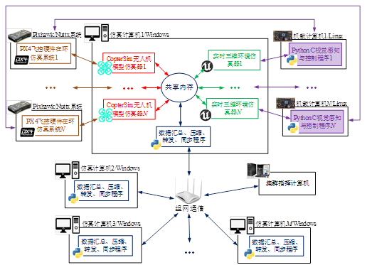
In this chapter, inter-process communication within each computer during swarm simulation uses shared memory for direct memory operations, achieving the lowest latency and highest speed. Each computer can run multiple SIL/HIL simulation systems to simulate multiple UAVs. Data sent and received by each computer is aggregated and compressed to ensure smooth network communication. Request-based communication is employed, supporting swarm simulation at the thousand-vehicle scale. For details, see: Chapter 10 — Swarm Coordination and Game-Theoretic Confrontation
Large-Scale Swarm Target Search Simulation
VTOL Multi-Aircraft Formation Flight
RflySim Cloud Introduction
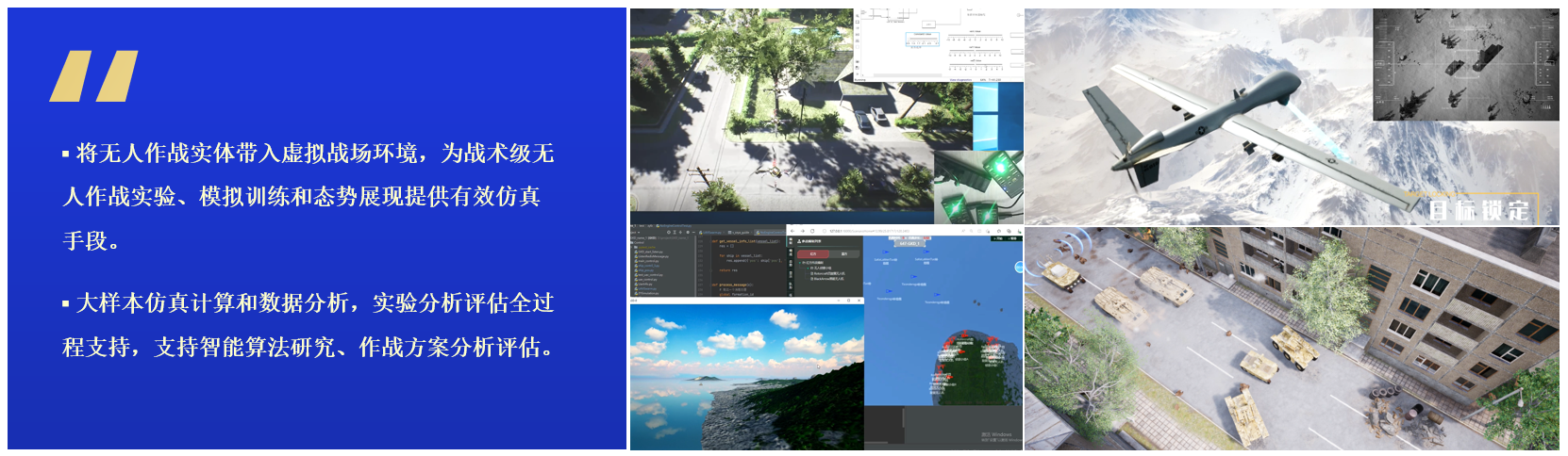
RflySim Cloud is an intelligent algorithm cloud platform developed by FeiSi Labs under Droneyee Intelligence for large-scale swarm algorithm verification, unmanned platform game-theoretic confrontation simulation, AI model training, and other cutting-edge research fields. It supports both public and private cloud deployment and serves as a comprehensive platform integrating large-scale high-fidelity model simulation with multi-type intelligent algorithm online development, debugging, and training.
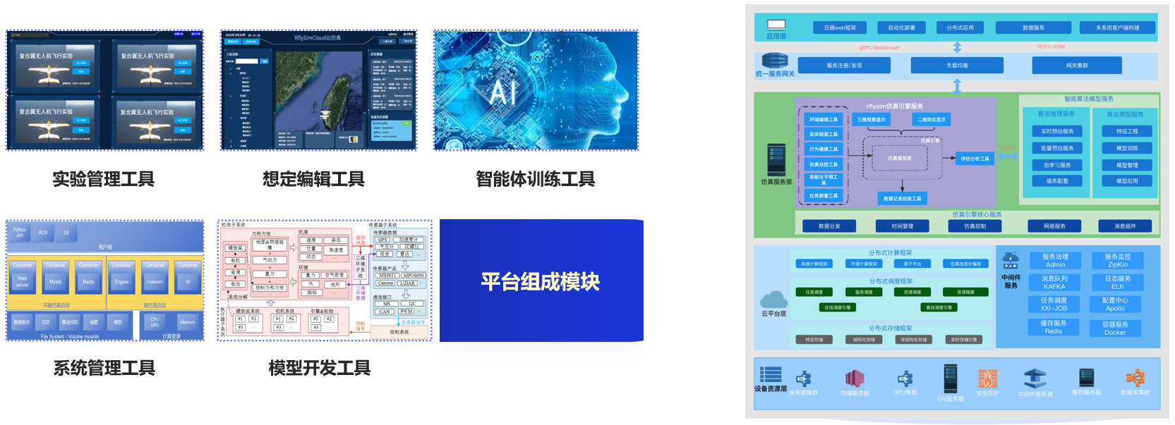
The RflySim Cloud platform consists of modules including experiment management tools, scenario editing tools, system management tools, agent training tools, and model development tools. End users only need to provide intelligent algorithms and dock them via the intelligent algorithm interface SDK; algorithms can then directly leverage modules such as system dynamics computation and multi-agent training.
Cloud-based access with ultra-high computing power support for ultra-large-scale swarm operations — free from local computing power constraints.