FOS i6s
1.product presentation
FS-i6S is a big initiative of Fusi to follow the classic and integrate new elements at the same time, i6S is a 10-channel transmitter, suitable for multi-axis, traversing machine, excavator and other engineering vehicle models, capacitive touch screen greatly enhances the user experience, both Chinese and English firmware to meet the needs of the vast majority of digital model friends!
2.Remote control configuration
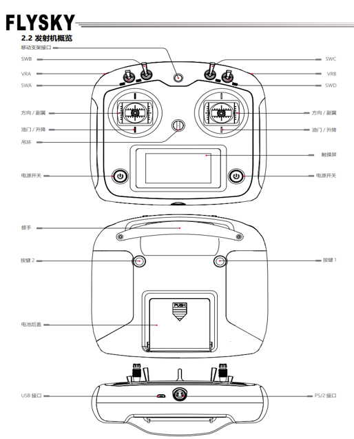
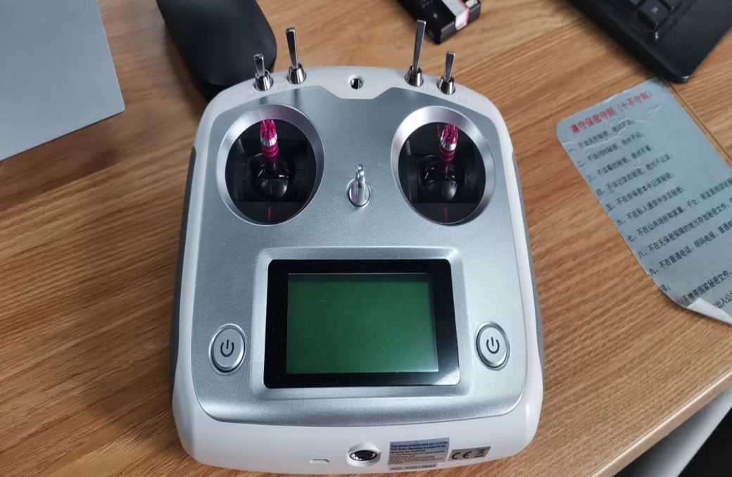
1)An overview of the transmitter is shown below.

2)Transmitter antenna: The FS-i6S transmitter uses a built-in copper tube omnidirectional dual antenna.
3)Joysticks/knobs/switches/keys: The FS-i6S has 2 sets of joysticks, 4 sets of switches, 2 sets of knobs and 2 sets of keys.
• Rocker: Used to control ailerons, lift, throttle and direction as well as auxiliary channels.
• Switch: Used to control the auxiliary channel or control timer.
• Knob: Used to control the secondary channel.
• Button: Used to control the secondary channel or timer.
4)Status indicator: The status indicator indicates the power supply and working status of the transmitter.
• Off: The power supply to the transmitter is turned off.
• Steady blue: The transmitter is powered on and operating normally.


Note: During use, in order to ensure signal quality, the antenna should be kept perpendicular to the model body. When operating, please adjust the antenna Angle to avoid the antenna tip direction pointing to the body. It is strictly prohibited to grip the transmitter antenna, otherwise it will greatly weaken the quality and strength of the radio transmission signal, resulting in the remote control failure model out of control. Do not pull the antenna of the receiver, and do not tie the antenna to the steering gear cable.
5)An overview of the receiver and transmitter is shown on the right.
6)Receiver antenna: FS-iA6B adopts copper tube omnidirectional dual antenna.
7)Status indicator: The status indicator is used to indicate the power supply and working status of the receiver.
• Off: The receiver power supply is not connected.
• Steady red: The receiver is connected to the power supply and is working properly.
• Fast blinking: The receiver is in the code matching state.
• Slow blinking: The paired transmitter is not turned on or the signal has been lost.
8)Interface: Interface is used to connect the receiver to the various components of the model.
• PPM/CH1: The steering gear connected to the CH1 channel or the output PPM signal.
• CH2 to CH6: ports are used to connect the steering gear, power supply, or other components.
• B/VCC: used to connect the code line during code alignment and power cable during normal operation. The power supply range is 4.0-8.4V.
• SERVO: Used to connect the i-BUS receiver extension channel and output i-BUS/S.BUS signals.
• SENS: connects sensors.
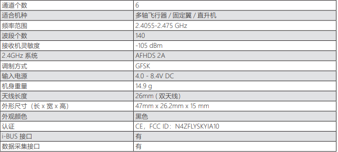
9)Receiver specifications (FS-iA6B) are shown below
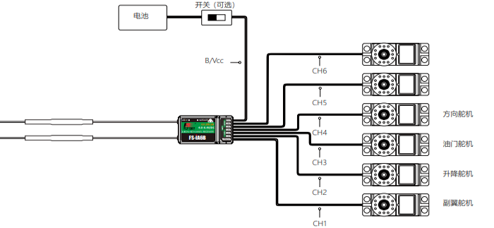
10)Receiver and steering gear installation: Install the receiver and steering gear as follows.


Note: FOss i6s remote control is mainly used for simulation, and its channel configuration method can be referred to the previous Ledi AT9S Pro.