Lotte AT9S Pro
1.product presentation
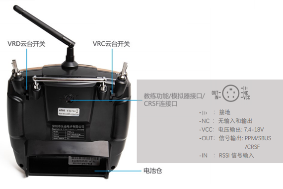
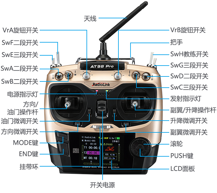
The AT9S Pro is a 12-channel transmitter that supports dual hybrid spread spectrum of 2.4G DSSS and FHSS, and 16-channel pseudo-random frequency hopping. Transmitter hardware description is shown in the following figure.
- Note: LeDI AT9S pro remote control is mainly used for indoor course experiments, and its price is also cheaper
2.Remote control configuration
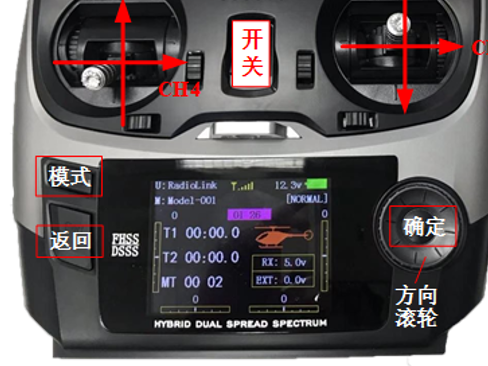
1)Flip the "switch" upward to turn on the remote control
2) Set language to Chinese and turn off sound
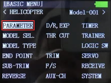
· Long press the "Mode" button on the remote control key panel,
· The model setup page in the lower left figure is displayed.
· Roll the "direction wheel" on the remote control,
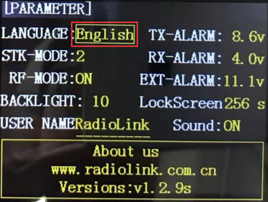
· Move the cursor to "PARAMETER" in the image above,
· Press the "OK" button on the right side of the remote control panel to enter the remote control parameter setting page,
· Scroll the "Direction wheel" on the remote control panel to select the entry "English".
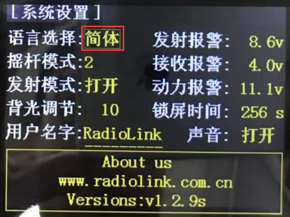
· Click the "OK" button on the remote control,
- · Then roll the "direction wheel",
- · Change the language to "Simplified" as shown below
- · Then click the "OK" button on the remote control to set the language to Chinese
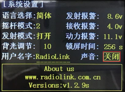
- · Adjust the sound option from "On" to "Off" by the same method as shown in the image.
3) Multi-rotor mode setting
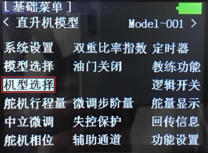
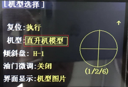
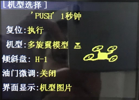
- · Long press the "Mode" button on the remote control panel to enter the "Basic Menu" setting interface as shown in the above picture, and click "Model selection" to enter the model selection page as shown in the above picture.
- · In the "Model" entry, change "Helicopter Model" to "Multi-rotor model", then long press the "Confirm" button on the remote control panel for more than one second, as shown in the picture above, to set the remote control mode to multi-rotor
4) Reverse the throttle channel Settings
- · The throttle channel in the multi-rotor mode of the Ledi remote is the opposite of the Pixhawk definition and therefore needs to be adjusted.
- · Long press the "Mode" button on the remote control panel,
- · Enter the "Basic Menu" setting interface as shown above, and select the "steering gear phase" entry.
- · In the "Steering gear Phase" entry Settings page, change the throttle from "positive phase" to "reverse phase".
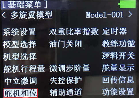
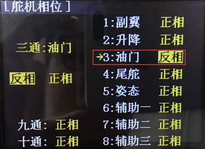
5) Set the CH5 mode switchover channel
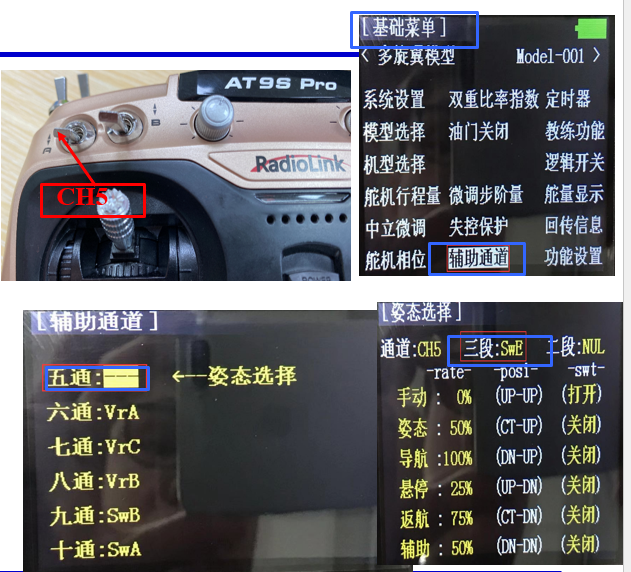
- · Due to experimental requirements, the fifth channel (CH5) of the remote control needs to be mapped as a three-segment switch in the upper left corner for mode switching of the controller.
- · Long press the "Mode" button of the remote control panel to enter the setting interface of "Basic Menu" as shown in the above picture, and enter the entry of "Auxiliary channel".
- · As shown in the figure above, enter the "Five passes" setting page, and map CH5 to the three-segment switch "SwE" of the remote control (front switch "E" in the upper left corner). Set the CH6-bit SwG in the same way.
6) Channel confirmation
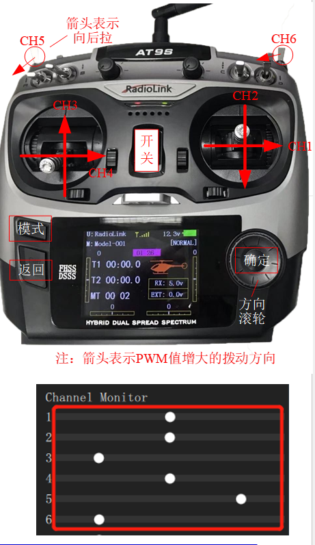
- · On the main page, press the "Back" button of the remote control, and the following "rudder quantity display" interface can appear. At this time, you can see the PWM value change of each channel by flipping each joystick.
Note: The top 100 of the yellow area in the following figure corresponds to the PWM value 1100 (the corresponding Channel slider in QGC's Channel Monitor is located on the left), and the bottom 100 of the yellow area corresponds to the PWM value 1900 (the corresponding channel slider in QGC's Channel Monitor is located on the right).
Due to the existence of various errors, the actual PWM signal received by the self-driving instrument is not exactly equal to the range of 1100-1900, for example, the range of the remote control is usually 1065-1933 (you can set the Parameters - Radio Calibration page in QGC as shown in the right figure).
Therefore, remote control calibration is essential for the autopilot to properly recognize the commands sent by the flight controller from the remote control. Remote control calibration can be implemented in the Radio page of the QGC ground station.

- · Flip each rocker in turn to ensure that each channel is correctly defined according to the following rules:
CH1: corresponds to the roll control, from left to right corresponds to the PWM value of 1100 to 1900(QGC's Channel Monitor slider 1 moves from left to right).
CH2: corresponds to pitch control, from top to bottom corresponding PWM value of 1100 to 1900. (QGC's Channel Monitor's # 2 slider moves from left to right).
CH3: corresponds to the throttle control, from top to bottom corresponds to the PWM value of 1900 to 1100 (note that here and CH2 is the opposite, QGC3 slider from right to left).
CH4: corresponds to yaw control, from left to right corresponding PWM value of 1100 to 1900.
CH5/6: Corresponding mode control, SE rocker (leftmost upper side), which is a three-segment switch, the top (the gear farthest from the user), the middle and the bottom (the gear closest to the user) gear corresponding PWM values of 1100, 1500 and 1900.
7) Hardware cables are connected
The preferred remote control for this simulation experiment is the LETI AT9Spro remote control and the supporting R9DS receiver
Necessary accessories include: battery (LiPo battery, 3S, 11.1V) and matching charger to power the remote control; JR wire (which can also be replaced by DuPont wire), used to connect the receiver to the Pixhawk autonomous vehicle; MicroUSB data cable for connecting Pixhawk self-driving device and computer.
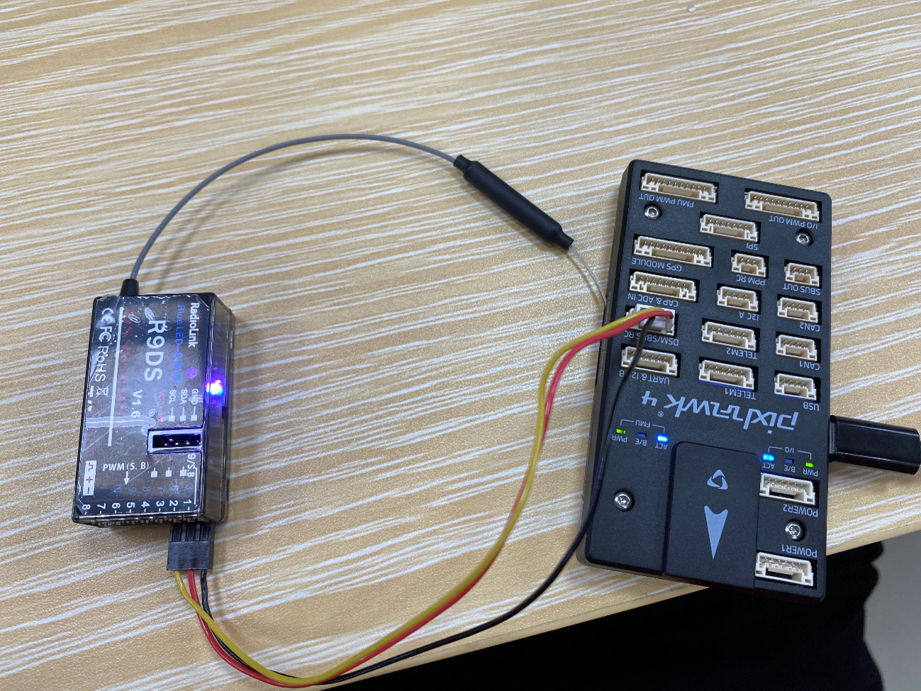
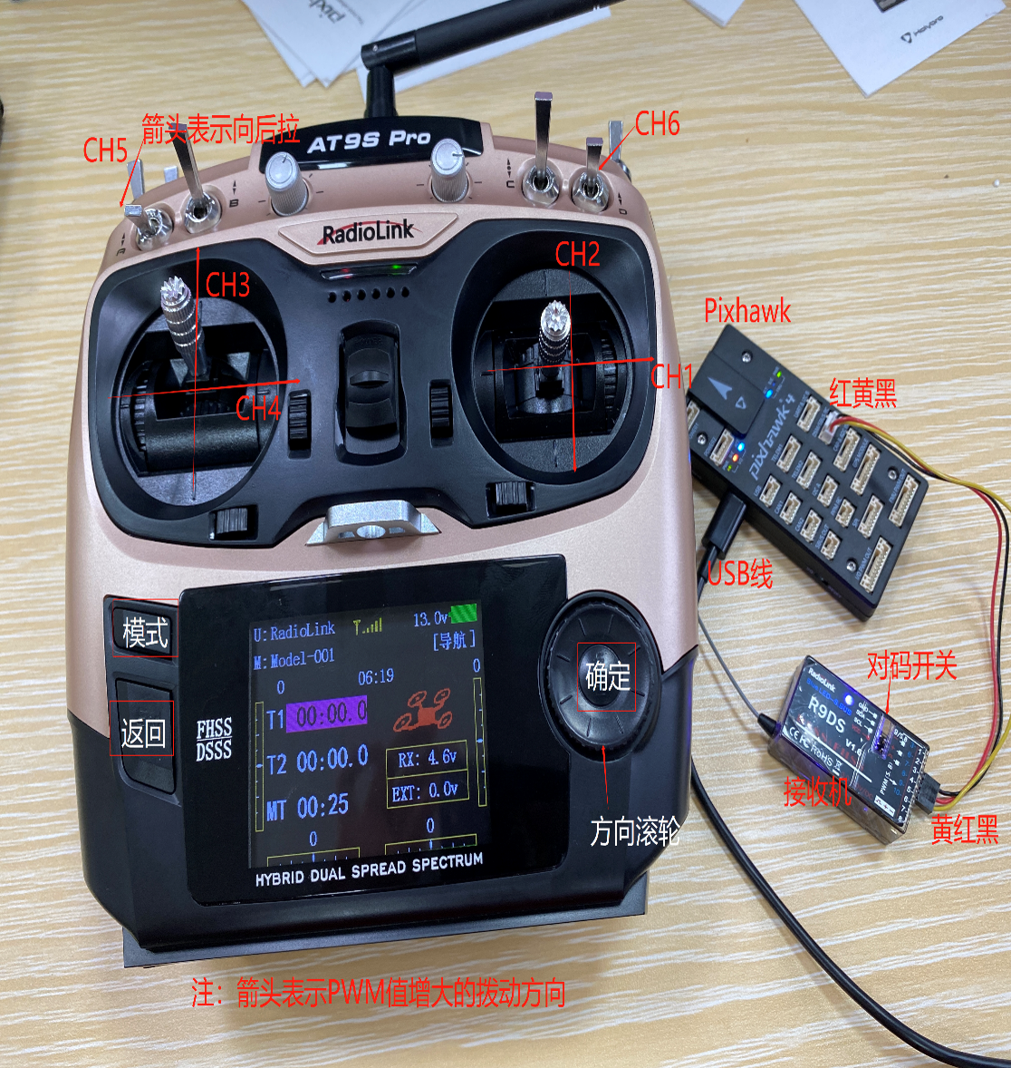
- · Connect the wire according to the figure above, connect the lower right side pin of the receiver to the leftmost pin of the flight control through the JR wire (pay attention to the wire sequence, the dark red LED light of the receiver indicates that the wire is connected backwards), connect the USB port to the USB port of the computer, and supply power to the receiver.
- · Remote control re-pair (the default is already connected, only need to re-pair if there is a connection problem). Turn on the remote control power, long press the button on the right side of the receiver with the pen tip for more than one second, then the LED light flashes, indicating to find the nearest remote control (other remote controls should be turned off at this time), and start coding. The LED light blinks 7~8 times and turns to steady on, indicating that the code is completed, and the remote control is connected to the receiver.
- · S.US signal mode selection. The S.BUS mode enables the transmission of PWM signals in all channels through a JR line, thus establishing the connection between the receiver and the flight control. If the LED light is blue and white, it indicates that it belongs to S.US mode at this time and does not need to be set. If the LED light is red, you need to press the button on the right side of the receiver twice (within 1 second), and the LED light turns blue and white, indicating that the S.US mode is switched.
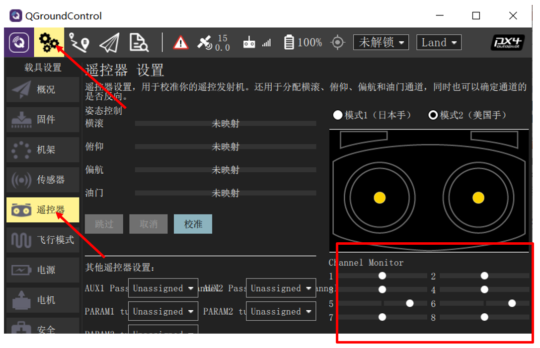
- · Check the correct connection method between the remote control and the receiver:
1, correctly connect the self-driving instrument and receiver, connect the self-driving instrument and computer with USB data cable, open the remote control, open the QGroundControl ground station software.
- After the ground station is successfully connected to Pixhawk, click the "gear" button as shown in the above picture to enter the setting page, and then click the "Radio" button (remote control) to enter the remote control configuration page in the above picture.
- If it can be observed that each Channel and slider are displayed under "Channel Monitor" on the far right of the above figure, and the rocker slider on the remote control will move accordingly, it indicates that the receiver has been configured and connected correctly. Otherwise, you need to reconfirm that the previous steps are correct.
- · Remote control battery installation method: Open the rear of the remote control lower battery slot (push down), plug the battery power supply head (red interface, there are two red and black wires corresponding to the positive and negative terminals) in the left two rows of the remote control battery slot plug, make sure that the positive terminal (red wire) face up.
Note: Do not use the USB port as the charging port, otherwise it will damage the transmitter, the port is used to upgrade firmware and copy data to the computer. It cannot be used as a controller on a computer.
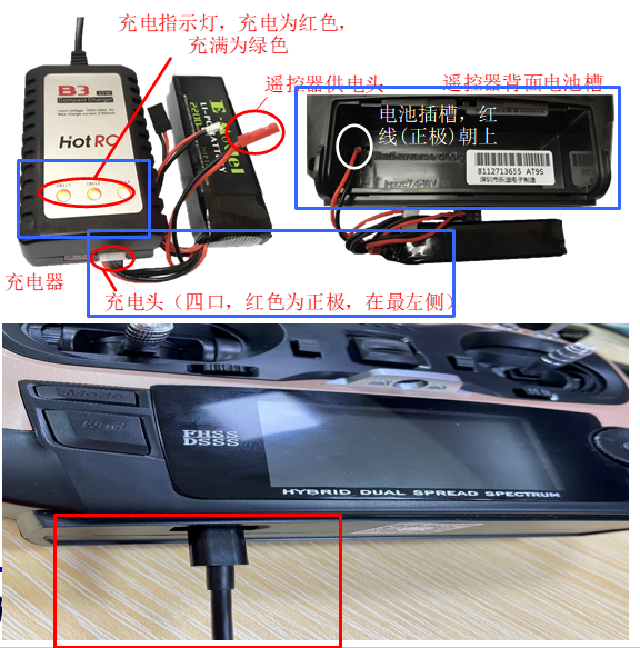
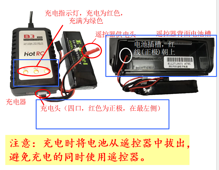
- · The left side of the figure below is the physical picture of the battery and charger. Plug the charger into the socket, and plug the four-port charging head (balance head) of the battery into the lower right port of the charger, and the red wire is on the far left side to start charging. When the charger is in the charging state, the indicator light of the charger is red. When the battery is fully charged, the indicator light turns green. At this time, the charging is complete.
8) Basic control Settings
- · Set the phase of the steering gear: for the multi-rotor model, just set the throttle to "reverse phase" here;
- · Set runaway protection: For multi-rotor models, only throttle runaway protection needs to be set.
Method:
I. Push the throttle lever down to the minimum, and then adjust the fine-tuning button next to it, and keep pushing down, listening to the prompt tone until it reaches the limit of adjustment.
Ⅱ. Select the throttle, long press "Push", select "reverse phase" in the box, push the throttle lever to the lowest, select the fine-tuning button next to it, play downward, and listen to the prompt tone until it reaches the limit of adjustment (the sound is a short sound).
· Auxiliary channel Settings:
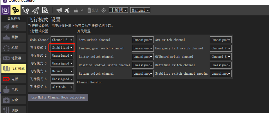
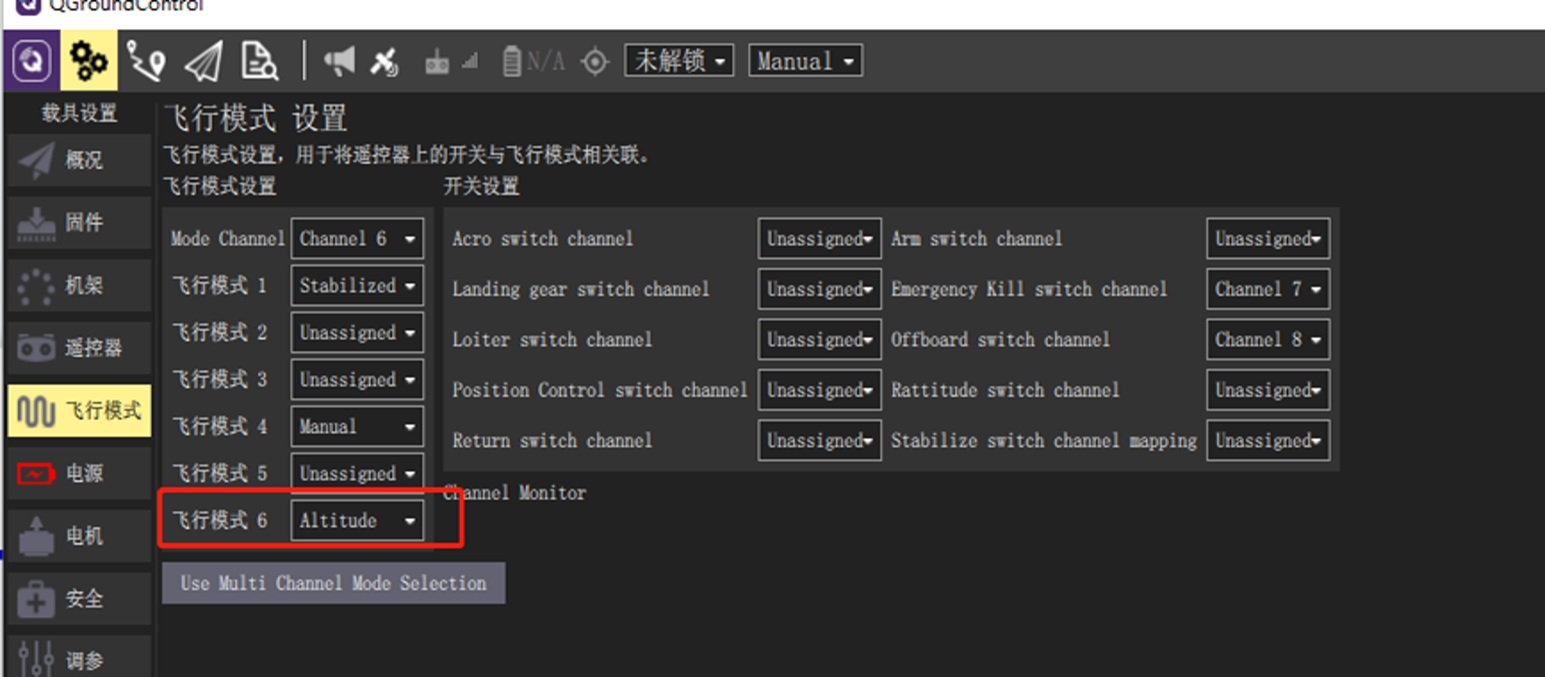
Select Six Channels ←-- Attitude selection channel: CH6 Segment 3: SwC Segment 2: SwD.
| rate | posi | swt | |
| 自稳: | 0% | (UP-UP) | (打开) |
| 悬停: | 20% | (CT-UP) | (关闭) |
| 定高: | 40% | (DN-UP) | (关闭) |
| 引导: | 55% | (UP-DN) | (关闭) |
| 降落: | 75% | (CT-DN) | (关闭) |
| 自稳: | 95% | (DN-DN) | (关闭) |
- SwC and SwD combine to select the flight mode
SwD SwC 飞行模式 ↑ ↑ 自稳(stabilized) → 悬停(Loiter) ↓ 定高(AltHold) ↓ ↑ Offboard(Offboard) → 返航(RTL) ↓ 降落(Land)
- Self-stabilizing mode (fixed wing)
The self-stabilizing mode puts the vehicle into a steady and level flight during the rocker return, maintaining attitude level and resisting wind (but excluding aircraft heading and altitude). If the roll/pitch rocker bar is not zero, the drone climbs/descends and performs a coordinated turn based on the pitch input. Roll and pitch are angle-controlled (can't roll up or down or cycle). If the throttle drops to 0% (motor stops), the aircraft will taxi. In order to perform the turn, the command must be maintained throughout the maneuver, because if the roll rocker is released, the aircraft will stop turning and level itself (the same is true for pitch and yaw commands). ** Note: The self-stabilizing mode can easily be used to keep the aircraft level by reversing the rocker.
3. Fixed height mode (Multi-rotor)
Set height mode is a relatively easy to fly remote control mode, roll and pitch rod control the body in the left and right and forward direction of the movement (relative to the "front" of the body), yaw rod control the horizontal plane rotation speed, throttle control the speed of rise-descent. When the rod is released/returned, the body will return to level and maintain its current height. If moving in a horizontal plane, the body will continue to move until any momentum is dissipated by wind resistance. If it is windy, the plane will drift in the direction of the wind. ** Note: For beginners, fixed height mode is the safest manual mode without GPS. Just like the self-stabilizing mode, but it also locks the body height when releasing the rocker.
4. Fixed Height mode (Fixed wing)
The fixed altitude mode makes it easier for the operator to control the altitude of the aircraft, especially to reach and maintain a fixed altitude. The mode does not attempt to resist wind disturbances to stay on course. The climb/sink rate is controlled by the pitch/elevator lever lever. Once the joystick is returned, the autopilot locks the current altitude and maintains it under yaw/roll and any airspeed conditions. Throttle channel input controls airspeed. Roll and pitch are angle-controlled (so it is not possible to roll or circle the aircraft). When all remote control inputs are centered (no roll, pitch, yaw, throttle about 50%), the aircraft will return to straight level flight (affected by wind) and maintain its current altitude.
5. Fixed-point mode (Multi-rotor)
The fixed point mode is a simple and difficult remote control mode, in which the roll and pitch rocker controls the acceleration of the body in the left and right directions relative to the ground (similar to the accelerator pedal of a car), and the accelerator controls the speed of ascent and descent. When the rocker is released/centered, the body will actively brake, remain level, and lock into position in 3D space - compensating for wind and other forces.
** Note: Fixed point mode is the safest manual mode for beginners. Unlike fixed height mode and self-stabilizing mode, the body stops when the rocker is in mid-position, rather than continuing until wind resistance slows it down.
Landing is easy in this mode:
1. Use roll and pitch lever to control the horizontal position of UAV above the landing point.
2. Release the roll and pitch bar and give it enough time to stop completely.
3. Gently pull down the throttle lever until the body touches the ground.
4. Pull the throttle lever all the way down to facilitate and accelerate landing detection.
5. The body will reduce the propeller thrust, detect the ground and automatically lock (default).
** Note: Although very rare on well-calibrated airframes, sometimes landing can be problematic. If the body cannot stop moving horizontally: you can still land in controlled altitude mode. The method is the same as above, except that you must manually ensure that the body remains above the landing point using the roll and pitch bar. Check GPS and magnetic compass directions after landing and calibrate. If the body does not detect the ground/landing and locks. When the body lands, switch to manual/self-stabilizing mode, keep the throttle lever low, and use hand gestures or other commands to manually lock. Alternatively, you can use the power off switch when the body is already on the ground.
6. Fixed Point mode (Fixed wing)
Spot-point mode is an easy-to-drive remote control mode where when the joystick is released/centered, the drone will fly horizontally in a straight line in the current direction - compensating for wind and other forces. Throttle depends on airspeed (at 50% throttle, the aircraft will maintain its current altitude at the preset cruising speed). Pitch is used for climbing or descending. Roll, pitch, and yaw are angle-controlled (so it is not possible to roll or circle the aircraft) Pitch, roll, yaw rocker centering - keeps the drone level with the ground in its current direction and resistant to wind. Tip: Fixed Point mode is the safest fixed wing manual mode for beginners. *