5.3、Frequently ISSUE
5.3.1、When MATLAB/Simulink performs code generation automatically, the following error sometimes occurs.
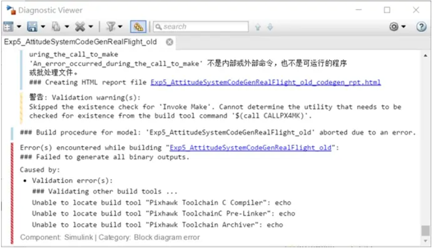
Caused by:
Validation error(s):
\### Validating other build tools ...
Unable to locate build tool "Pixhawk Toolchain C Compiler": echo
Unable to locate build tool "Pixhawk ToolchainC Pre-Linker": echo
Unable to locate build tool "Pixhawk Toolchain Archiver": echo
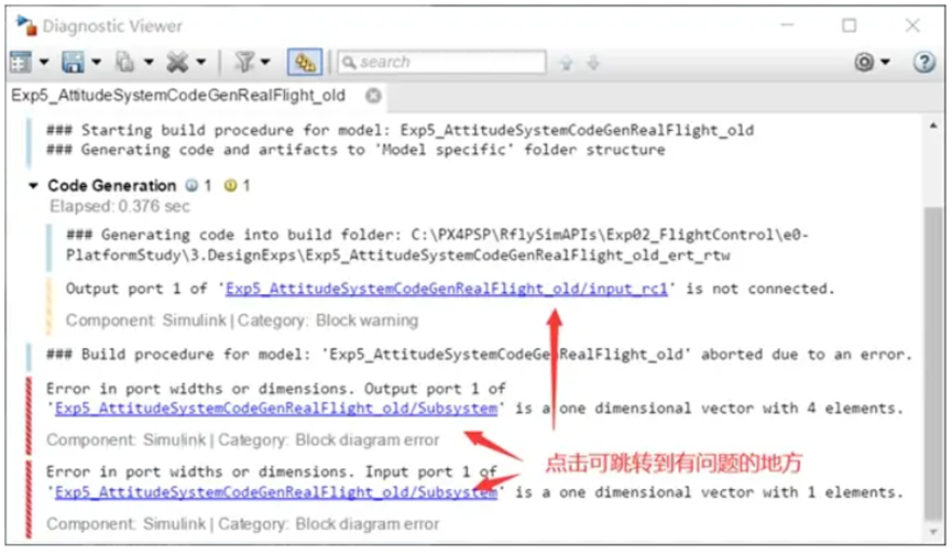
If there is a compilation error, the possible compilation problems can be divided into: MATLAB model problem, PX4 firmware problem, MATLAB model and PX4 firmware link problem.
Answer to questions: Deal with MATLAB model issues. MATLAB automatic code generation checks the model at the initial stage of compilation, so such problems tend to show up within seconds of clicking the compile button. The most common MATLAB problem is that the data of each interface does not match. Click on the wrong module to jump to the problem.
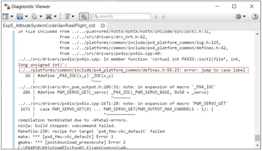
Handle PX4 firmware issues. If there is a compilation problem with the PX4 source code, it will generally be displayed in the MATLAB compilation log prompt. The following figure shows the location of the problem code, and modify it according to the prompt. The firmware of PX4 in the platform is located in PX4PSP\ Firmware.
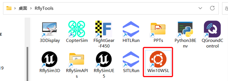
Handle the link between MATLAB model and PX4 firmware. This kind of problem is often that some interfaces change due to the upgrade of PX4 firmware, and the interfaces generated by MATLAB automatic code may not match, so an error will occur in the final link phase. No specific errors can be found in MATLAB for this kind of problems. You need to open Win10WSL (select other compilation tools and refer to other tools) and re-execute the compilation commands such as make px4_fmu-v6c_ default (other versions are replaced with their corresponding commands) to see the specific problems.
5.3.2、In the automatic code generation controller, the delay module is used to generate control instructions directly, causing the aircraft to fly randomly.
Problem description:
In the routine: PX4PSP\ RflySimAPIs\ Exp02_FlightControl\ e5-AttitudeCtrl\ E5.1\ HIL disconnect the remote control input CH1-CH4 from the inputConditioning module, change the input signals of roll (CH1), pitch (CH2), throttle (CH3) and yaw (CH4) to the fixed value input we want, only modify AttitudeControl_HIL.slx in this place, and then do hardware-in-the-loop simulation with the same operation steps as the original AttitudeControl_HIL.slx routine. After starting the hardware in the loop, the plane itself flies around on the ground, and an error will appear after a while. What is the reason for this? What should we do about it?
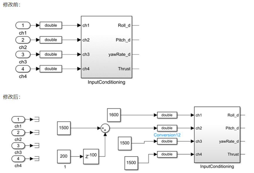
Simulation phenomenon: after the change, during the hardware-in-the-loop simulation, the UAV flies around on the ground.
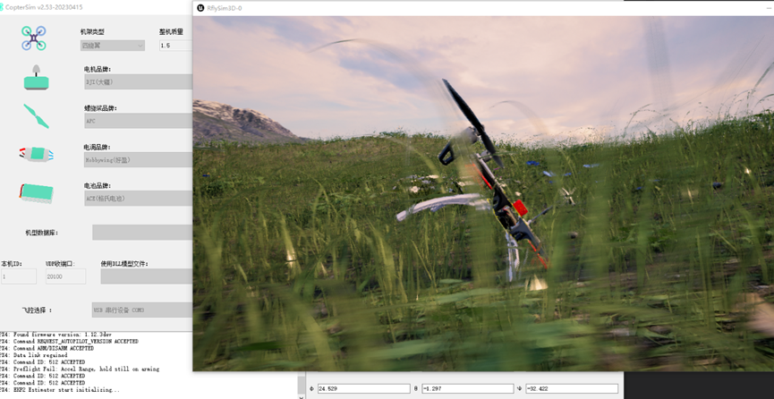
This modification is not feasible because the 200 step delay is only 200 seconds, 0.001 seconds and 0.2 seconds. But the px4_simulink_app program starts running as soon as it is powered on, it is equivalent to entering the control instruction after the power-on, which becomes the throttle state. In this case, the flight control has not been initialized, the filter triggers the divergence state, and the accurate position and attitude information is not obtained.
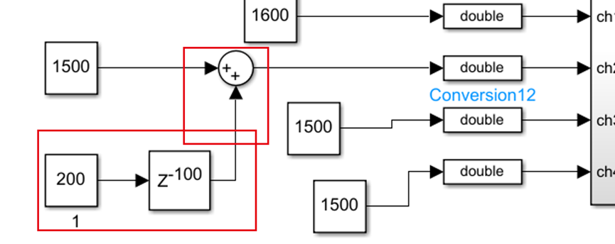
Perfect scheme: read the uORB message of EKF state directly, judge that the filter is initialized, and then delay the control instruction for a period of time. Simple solution: increase the delay time a little bit, or directly write a trigger mechanism with the MATLAB function, and then give control instructions after the simulation time reaches 60s.
5.3.3、How to do autonomous attitude control of UAV?
Problem description:
The detailed description is as follows: we need to let the UAV fly to a certain height, and then input according to our own given attitude angle expectation, let the UAV act independently, and make the three attitude angles move to the given expected value.
Answer to questions:
The channel of the remote control can be used to transmit trigger information, for example, when the CH5 is dialed to the full position, the program starts to execute automatically, write a state machine in the Simulink, let the plane take off first, wait until the altitude is reached, and then attitude control. The specific controller design method belongs to the category of Simulink programming, which can be understood by consulting the relevant literature. If you want to enter the desired attitude angle from the outside after switching height, please use the external control interface in the0.ApiExps\9.PX4CtrlExternalTune\Readme.pdf directory to subscribe to the rfly_ctrls message (passed in by the external program) in the flight control as the desired attitude angle.
5.3.4、How to get the result data of attitude control hardware in the loop? Can I get what I want from the way I know how to download the flight log?
Answer to questions:
Use the interface of the 0.ApiExps\ 9.PX4CtrlExternalTune\ Readme.pdf routine to obtain the real attitude (simulation value) of the model in Simulink and the data from the flight control (fill in the flight control attitude) in real time, and similar data can be obtained from the flight log.
5.3.5、When WinWSL compiles firmware, it displays: region `AXI_SRAM' overflowed by 15401072 bytes
Problem description:
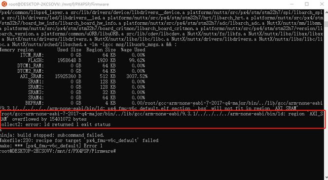
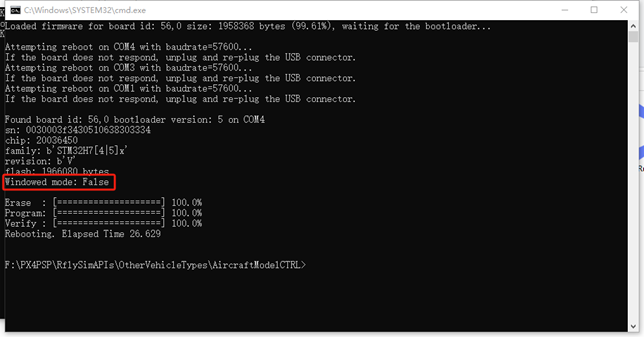
Answer to questions: The problem is that the compiled firmware is larger than the content of flight control, resulting in firmware overflow error. You can enter the Cmake file of PX4 to comment out some unused modules. The specific address of Pixhawk series flight control is: *\PX4PSP\Firmware\boards\px4. For example, the experiment carried out is the four-rotor related underlying control algorithm development experiment, the flight control used is Pixhawk 6C, C:\PX4PSP\Firmware\boards\px4\fmu-v6c\ default.cmake, the unused modules in this file are annotated (below), and then compiled.
……
    MODULES
        airspeed_selector
        px4_simulink_app
        attitude_estimator_q
        camera_feedback
        commander
        dataman
        ekf2
        esc_battery
        events
        flight_mode_manager
        # fw_att_control      Comment out the fixed wing attitude control module
        fw_pos_control_l1
        gyro_calibration
        gyro_fft
        land_detector
        landing_target_estimator
        load_mon
        local_position_estimator
        logger
        mavlink
        mc_att_control
        mc_hover_thrust_estimator
        mc_pos_control
        mc_rate_control
        #micrortps_bridge
        navigator
        rc_update
        rover_pos_control
        sensors
        sih
        temperature_compensation
        # uuv_att_control     Comment out the UUV attitude control module
        # uuv_pos_control     Comment out the UUV position control module
        vmount
        # vtol_att_control    Comment out the VTOL attitude control module
……
5.3.6、Which version of RflySim's mavlink is used?**
Answer to questions:
The routine for our RflySim platform is MAVLINK 2
5.3.7、How is the position information sent to flight control in QGC Mission mode accepted?
Answer to questions:
It is similar to the fixed point, except that the fixed point only sends one, and when the Mission reaches a point, the next one is sent.
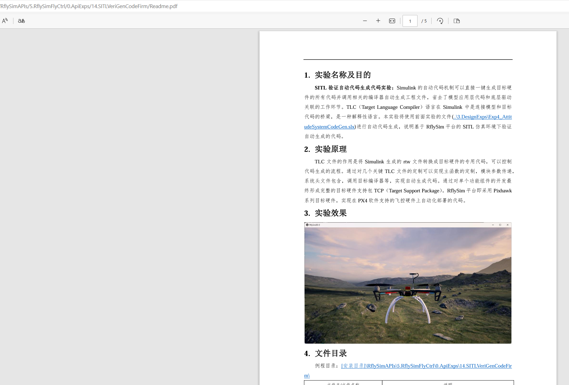
5.3.8、The new version of readme writes "automatic code generation supports SITL simulation", may I ask if this means that simulink automatic code generation can support make px4_sitl_default? I tried to make or report an error, but I did not find the documentation of this problem before, I would like to ask what is the situation?
Problem description:
As shown below:

Answer to questions:
【RflySim installation directory 】 \RflySimAPIs\5.RflySimFlyCtrl\0.ApiExps\14.SITLVeriGenCodeFirm\Readme.pdf Look at this routine, as shown in the following picture: You cannot run make px4_sitl_default directly. You need to run a MATLAB command to switch, then run SITLRun, and you can carry out software-in-the-loop simulation with the automatic code generation controller.
5.3.9、Using the RflySim platform, compile your own model in simulink, and then burn it to pixhawk with the code upload button of RflySim, is it completely replacing the original px4 firmware burned at first?**
Answer to questions:
Not completely replace, just replace the controller.
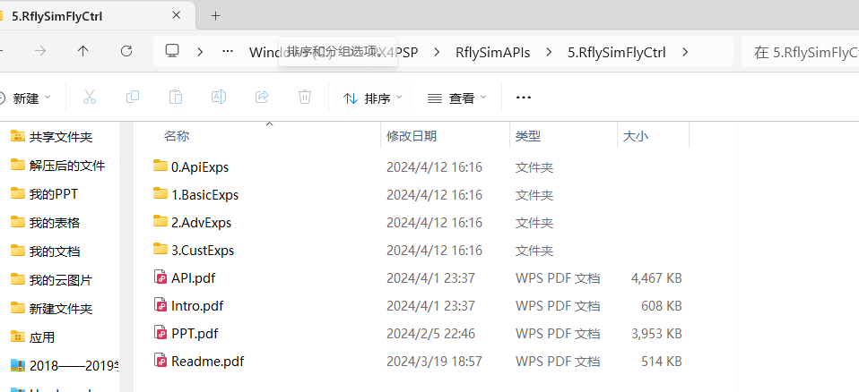
5.3.10、Can you provide the relevant code of the development training course on the website B? I see the code in the github warehouse of RflySim platform, most of them are different and different, and then the relevant files of the turntable experiment are not found on github.**
Answer to questions:
You can download and install the new version of the platform, all the routine files of the training course are in: 【 installation directory 】 \PX4PSP\RflySimAPIs\5.RflySimFlyCtrl, as shown below:
5.3.11 、When doing hardware in the loop simulation, the value of actuator_output is not the value calculated by me. According to qgc, there seems to be two places output at the same time. What is the reason?
Answer to questions:
Select "Yes" for the last item when installing the platform. As shown in the picture below:

5.3.12、May I ask whether to change the parameter of the.m file or the param.c file when making hardware in the ring? It seems that there is no change in the.m file?**
Problem description:
As shown below:

Answer to questions:
This experiment burned to the flight control in the connection of QGC can directly modify the controller parameters in QGC.
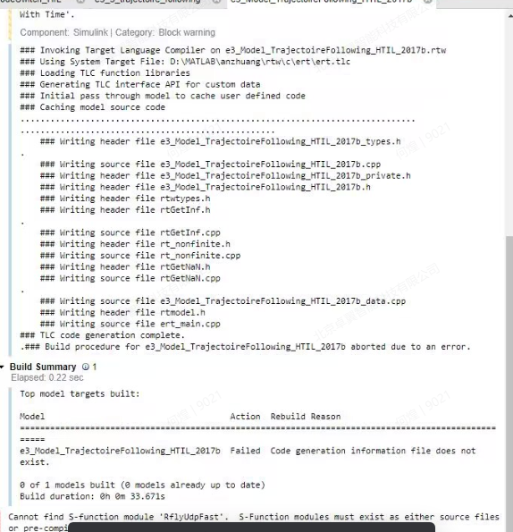
5.3.13、In the tutorial case for hardware in the ring when this error, what is the reason, you can run the normal simulation, is not compiled, matlab using 2020b, installed vs2017, how to solve?
Problem description:
As shown below:
Answer to questions:
The file is not complete. The RflyUdpFast.cpp file is not copied
5.3.14、Every time after the hardware of the uORB read and write test is in the loop, the sensor data such as the compass and accelerometer of the flight control cannot be read in the QGC setting. The sensor option is not displayed, and the firmware cannot be rebrushed. What is the cause?
Answer to questions:
The sensor page will be displayed only when the rack is set to a real aircraft frame
5.3.15、The output of simulink controller was released through PWM_output module, compiled and downloaded to pixhawk, and data inconsistency was found after the motor output was detected. I have blocked the output of px4 official controller, what is the reason for this?
Answer to questions:
If you write your own controller, you may not understand the input and output of the controller accurately. If the pwm pulse width is written directly in the program, it is that the observation method does not read the correct data
5.3.16、Can the flight control send data to the specified uart port through simulink program? Is there a similar routine?
Answer to questions:
You can refer to the "5. RflySimFlyCtrl \ 0. ApiExps \ 2. PSPOfficialExps/px4demo_Serial_TxRx SLX" this example.
5.3.17、Reference 5 rflysimflyctrl/e6PosituonCtrl, using simulink generated by the controller to replace the px4 controller, the output of PWM, set up the expectation of fixed position and the desired yaw 0 (0,0,2), and detect the pixhawk unlock before sending to calculate the PWM, otherwise 0. After starting HitlRunLowGpu, wait for the attitude estimation initialization to complete, unlock through the remote control, but the drone will fly around. The custom controller has been verified by pure simulink, and the corresponding coordinate transformation should be no problem. Because there are some integrals inside the controller, I want to record some variables inside the controller. Can I record it through CopterSim? Found a way to introduce and record the status of the drone (position, motor speed, etc.), but did not find a way to record the intermediate variable?
Answer to questions:
Question 1- Aircraft flying: need to send a screenshot of your controller, or a file (file can be added to me)
Question 2- Intermediate variable record method: you can customize the uORB message and then see the log, the corresponding routine see: \RflySimAPIs\5.RflySimFlyCtrl\0.ApiExps\7.uORB-Create, you can also write the variable to the.bin file stored in the sd card, the corresponding routine see: \RflySimAPIs\5.RflySimFlyCtrl\0.ApiExps\5.Log-Write-Read. The corresponding routine for CopterSim data logging can be seen: *\RflySimAPIs\2.RflySimUsage\1.BasicExps\e13_Log-Get
5.3.18、I want to input the x, y, z coordinates directly and send the vehicle over, how do I input those coordinates, how do I send those coordinates to the flight control to execute? Are there any examples?
Answer to questions:
The official controller can use mavlink/offboard, write your own controller, you can use rfly_ctrl interface RflySimAPIs\5.RflySimFlyCtrl\0.ApiExps\9.PX4CtrlExternalTune