7.1 How to Use This Chapter
RflySim adopts the Model-Based Design (MBD) philosophy for control and safety testing of unmanned systems. The development workflow consists of five stages: modeling → controller design → Software-in-the-Loop (SIL) simulation → Hardware-in-the-Loop (HIL) simulation → real flight testing. Through MATLAB/Simulink automatic code generation technology, the controller can be seamlessly downloaded to hardware for HIL simulation and real flight testing.
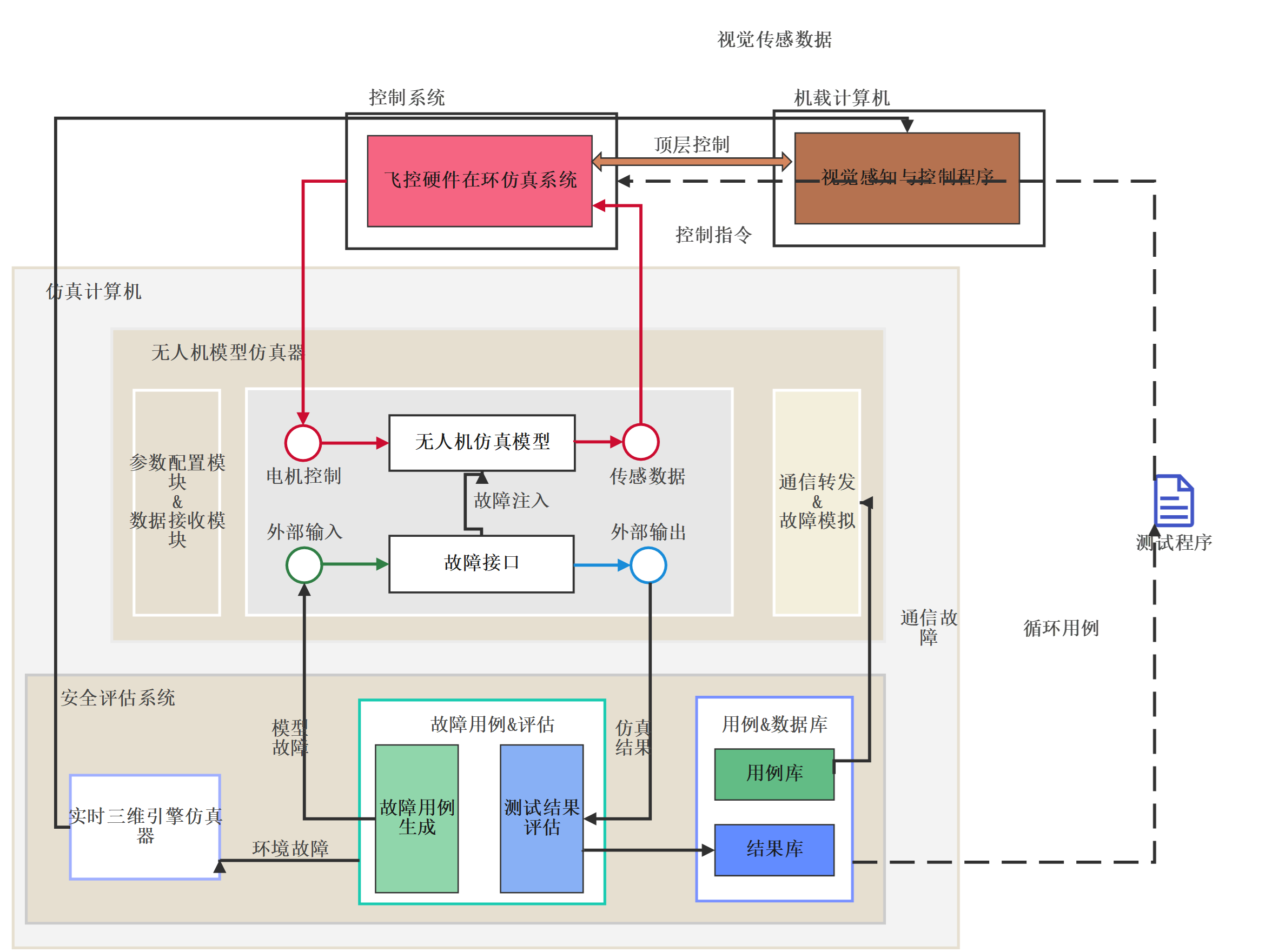
The RflySim fault injection architecture consists of three modules: the physical module, simulation module, and evaluation module. The physical module comprises the flight control hardware, responsible for connecting with the simulation computer, receiving external control commands, and making attitude responses to form a semi-physical simulation closed loop for real-time HIL fault injection. The simulation module consists of CopterSim, RflySim3D, and QGC, responsible for sending fault messages, performing full-vehicle 3D fault injection, and running real-time fault simulation. The evaluation module outputs the safety status after fault injection.
Chapter Introduction Document
The introduction document for this chapter is located at: 🔗[Installation Directory]\RflySimAPIs\7.RflySimPHM\Intro.pdf🔗
API Reference
The development API reference for this chapter is located at: 🔗[Installation Directory]\RflySimAPIs\7.RflySimPHM\API.pdf🔗
PPT Courseware
The PPT courseware for this chapter is located at: 🔗[Installation Directory]\RflySimAPIs\7.RflySimPHM\PPT.pdf🔗
All Example Files
For all examples in this chapter, see the Readme documentation located at: 🔗[Installation Directory]\RflySimAPIs\7.RflySimPHM\Readme.pdf🔗