8.3、Frequently ISSUE
8.3.1、What is the internal parameter matrix of the depth camera?
Answer to questions:
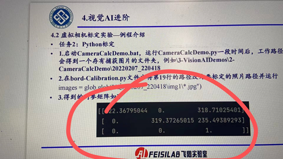
The internal parameter matrix of a depth camera describes the internal parameters of the camera, including information such as focal length, main point position, and camera distortion. Typically, the internal parameter matrix is a 3x3 matrix, usually expressed as: [K = \begin{bmatrix} f_x&0&c_x \ 0&f_y&c_y \ 0&0&1 \end{bmatrix}]
Where, (f_x) and (f_y) are the focal lengths of the camera in the horizontal and vertical directions, and (c_x) and (c_y) are the coordinates of the camera's principal point position (optical center). In general, the primary point position is the coordinate of the center of the image. The last line is usually ([0, 0, 1]), representing the scale factor of one unit.
For depth cameras, the value of the internal parameter matrix will vary depending on the specific camera model and parameter Settings. You can get specific values for the internal parameter matrix by consulting your camera's technical specifications or documentation. In addition, some depth cameras may also take into account distortion parameters, such as radial distortion and tangential distortion, which can also be included in the internal parameter matrix.
As shown in the image below:
8.3.2、How can the developed face recognition algorithm or height control algorithm be transplanted to the simulation environment or verified in the simulation environment?
Answer to questions:
Face recognition examples, you can use Python to write, do experiments in the platform. After the image source, from our platform to the corresponding camera on the line. Or directly use the NX hardware-in-the-loop mode, directly develop the algorithm in C++ and ROS environment, and perform hardware-in-the-loop visual simulation, and then directly access the NX to the real machine, adjust the image source to the camera, you can carry out the real flight. The altitude control algorithm is directly placed in Simulink, and burned into the flight control through the process of low-level flight control development in the second lesson
8.3.3、during software simulation, how to apply the python algorithm implemented by myself to the software, is there any specific documentation of the API that should be called? Is there a demo code process to explain the implementation?
** Answer to questions: **
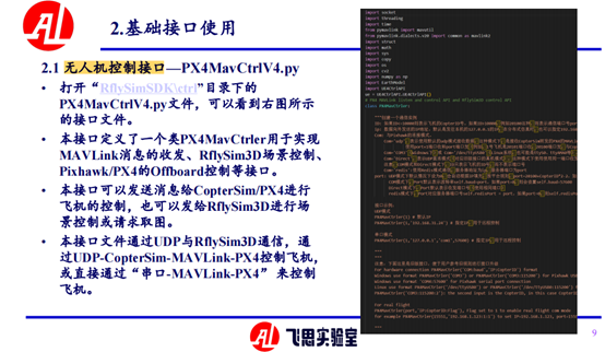
Refer to zhang PPT2.1 section 8, path is: [install directory] / RflySimAPIs / 8. RflySimVision/PPT. PDF as shown in the figure below:
8.3.4、May I ask how to modify the UAV flight path in the routine to match the trajectory points generated by the target search algorithm to the waypoint of UAV flight, or how to input the location parameters of the trajectory points generated by our search algorithm to the UAV, so that it can fly according to the given position?
Answer to questions:
1.Using the PX4MavCtrl.py interface provided by the platform to send points on the trajectory, of course, there needs to be a judgment mechanism to judge and reach the point. The general interface getPos is used to obtain the current position of the aircraft, and then the judgment mechanism is invoked.
SendPosNED(); SendPosFRD(),SendPosXXX(), such as the function interface starting with SendPos, need to pay attention to the difference between the coordinate system, necessary coordinate conversion;
2.Use mavros to send the mavlink command to publish the topic /mavros/set_position/local or /mavros/setpoint_raw/local, To obtain the position of the aircraft through the topic /mavros/local_position/pose, the same as the interface provided by the platform requires a judgment mechanism and changes between coordinate systems.
8.3.5、depth camera in addition to depth can also know the pixel and the actual camera left, right, up and down distance?
Answer to questions:
Depth cameras usually provide the 3D coordinates of a pixel in the camera coordinate system, which includes information about the distance of the pixel from the actual left, right, up and down of the camera. This distance information can be obtained by converting the depth value of the pixel (also known as the parallax value) to the actual distance in the camera coordinate system.
Based on the depth value of the pixel provided by the depth camera and the internal reference matrix of the camera, the actual distance of the pixel in the camera coordinate system can be calculated using triangulation or the geometry of the depth image. This process is called depth resolution or depth restoration of a depth image.
Once the depth value of the pixel is converted to the actual distance in the camera coordinate system, information about the distance of the pixel from the actual left, right, up and down of the camera can be obtained. This distance information can be used to perform various calculations and applications, such as object distance estimation, attitude estimation, 3D reconstruction, etc.
8.3.6、How to get the true pose in RflySim, and how to set the use of visual positioning
Answer to questions:
The RflySim platform is transmitted through mavlink, corresponding to ros, you can subscribe to mavros published pose topic acquisition, for the interface provided by the platform PX4MavCtrlV4.py there are related interfaces. To use visual positioning, you need to set the EKF2_AID_MASK parameter in QGC, set it as the data source from the vision on the line, and set the EKF2_HGT_MODE value to vision. In addition, the position and pose of visual positioning can be sent to mavros
8.3.7、json file in addition to setting the image resolution, can you set the pixel size? What is the default pixel size
Answer to questions:
RflySim platform config does not support pixel size customization for the time being.
8.3.8、How can I modify the field of view of RflySim's liDAR? Can I change it to 64-line?
Answer to questions:
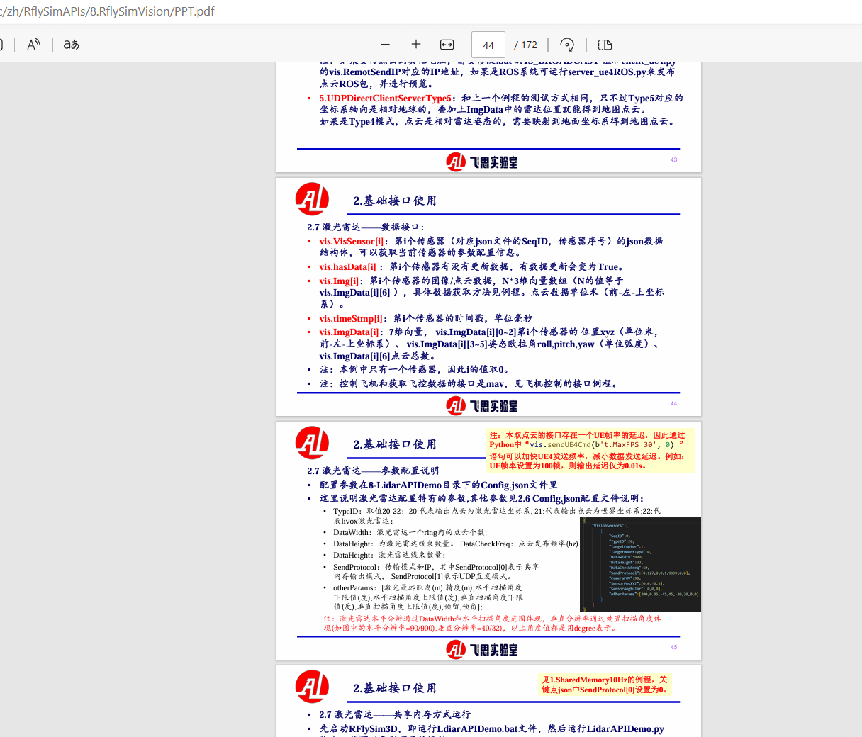
Can be changed to 64 lines, harness to DataHeigh, resolution according to DataWidth and field of view Angle change. Specific platform laser radar parameters and code parsing can reference path is: [install directory] / RflySimAPIs / 8. RflySimVision/PPT. PDF as shown in the figure below:

8.3.9、How to obtain the image captured by px4's simulation camera in gazebo at qgc ground station?
Answer to questions:
Obtaining images captured by the PX4's camera in Gazebo's simulation environment at the QGroundControl (QGC) ground station usually requires the use of a few additional tools and tricks. Here's one possible way to do it:
Set up the camera model in Gazebo:First, ensure that the corresponding camera model has been added in the Gazebo simulation environment and that the model is correctly set.
Start the PX4 simulation:Start the simulation with a PX4 simulator (e.g. jMAVSim or Gazebo) and make sure that the simulator is properly connected to the QGC ground station.
View Gazebo image topic: While the emulator is running, you can get the image captured by the camera by viewing the image topic published in the Gazebo simulation environment. Normally, the name of the image topic depends on the name of the camera model you set in Gazebo and the topic type of the image (e.g. RGB image, depth image, etc.).
Use the ROS tool: If you use ROS (Robot Operating System) in your simulation environment, you can go through the ROS tool
Use the ROS Bridge:If QGC supports the ROS Bridge function, you can use the ROS Bridge to forward the image topic in ROS to QGC, so that you can view the image in QGC. This requires some additional setup and configuration, depending on your system and environment.
Note that the exact steps may vary depending on which version of PX4, Gazebo, and QGC you are using. It is recommended to consult the appropriate documentation or contact the relevant community for more detailed guidance.
8.3.10、the ROS control examples in the vision we have on the platform now, what is used to control the real machine? For example,the kind of path planning in the future.
Answer:
Can also be controlled by ROS, pay attention to data source switching when code migration.
8.3.11、when I make tensorrt, I always report an error?
Answer to questions:
This is a library problem. It could be that the C++ compiled version does not match and the code uses higher version features above C++11.
8.3.12、A RflySim environment, and then two UAVs onboard computer software simulation in the loop, must be configured sensor parameters?
Answer to questions:
In addition to ip, the two UAV-borne computers also have special sysid identification, RflySim3D computer side, client config needs to contain all cameras, and server config needs to be configured separately for the corresponding aircraft. First determine how many planes you want to create in RflySim, and then configure the sensors according to the ids of the planes
8.3.13、Does the RflySim platform camera model support distortion parameters, such as main point translation, etc.?
Answer to questions:
The camera of the RflySim platform is the ideal model with no distortion. Even when calibrated using the calibration board, the internal parameter matrix will be close to the ideal value.
8.3.14、Can you provide through the ring, impact ball, face recognition source code annotation?
Answer to questions:
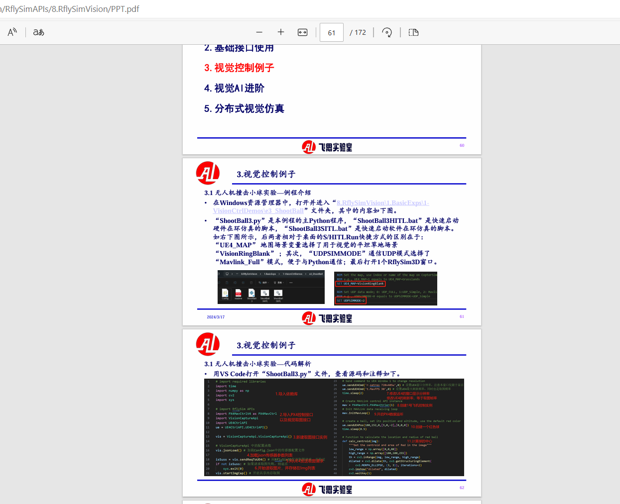
In chapter 8 PPT have comments in section 3, the path is: [RflySim installation directory] / RflySimAPIs / 8. RflySimVision/PPT. PDF as shown below:
8.3.15、How realistic is the simulation environment, such as: gravity, magnetic field, air pressure, physical engine (air resistance, motor torque, collision), sensors (barometer, gyroscope, accelerometer, compass, GPS)
Answer to questions:
Gravity, magnetic field, air pressure and other models are all mature modules in Simulink, using the latest international standardized models. The air resistance model is currently fitted according to the real flight data, and the fidelity needs to be corrected with the experiment; The sensor model is also mostly using the current mature model, which can be verified by comparing the experimental data with the simulation data.
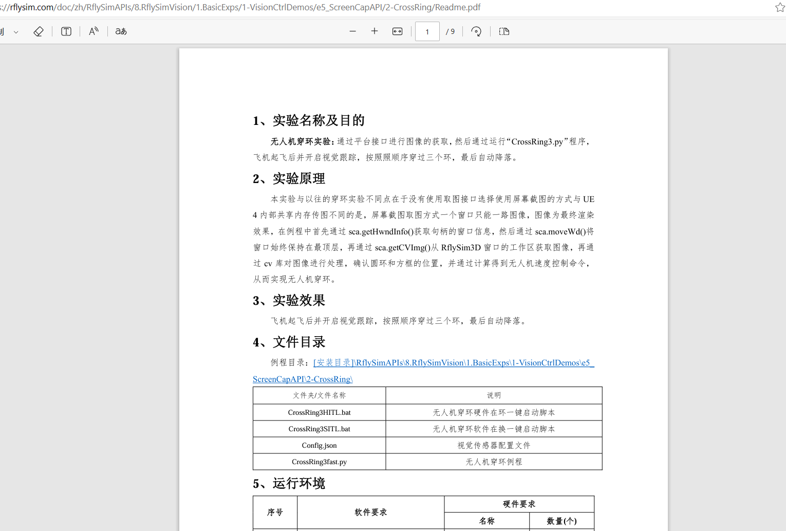
8.3.16、What are the three meanings of python Vision piercing routine respectively?
Answer to questions:
This routine is the remote implementation of the piercing, and config is the configuration file. client runs under windows and server runs under linux. The specific routine can be referred to: [installation directory]\RflySimAPIs\8.RflySimVision\1.BasicExps\1-VisionCtrlDemos\e5_ ScreenCapAPI\2-CrossRing. As shown in the following picture:
8.3.17、May I ask the RflySim simulation platform, two drones do visual-related collaborative algorithms, the first aircraft camera perspective I can read out, the second by changing the parameters can only read the first perspective, or is empty, there is a big know how to set the second aircraft camera parameters?
Answer to questions:
json file parameters are not set correctly, SeqID is different, a 0, a 1 will do.
8.3.18、Current visual perception and control, on-board computer semi-physical transplantation, are there related tutorials?
Answer to questions:
This tutorial is being refined. The latest version of the platform can run down the scene of our robot race. C:\PX4PSP\RflySimAPIs\8.RflySimVision\1.BasicExps\2-BaseDemoAuto
- At present, our WinWSL is Ubuntu 20.04, which is basically the same as the on-board computer except that it does not use GPU acceleration. In the initial simulation, the algorithm is generally developed in WinWSL, the image data is subscribed by ROS1/ROS2, the algorithm is developed, and the aircraft is controlled by mavros.
- Copy the algorithm directly to the real machine board, do GPU acceleration or optimization for the board, and conduct flight control and board card simulation in the loop (you can also buy our vision box with flight control and onboard board)
- Copy the algorithm to the real computer board and modify the ROS subscription image source from the original simulation image ROS message to your own camera ROS message; And with the real camera parameters, it can be achieved.
- At present, the algorithm of our robot competition is to take three steps and fly directly on the real plane. A more detailed tutorial should be released with version 3.05 in the near future, and this work is currently being sorted out, and you can also pay attention to our summer training at that time.
8.3.19、May I ask whether the current UAV navigation, visual stability and reliability or laser solution is better?
Answer to questions:
Indoor use of laser, low altitude outdoor is not easy to say, need to choose the appropriate sensor scheme according to the application scenario, but comprehensive consideration, recommend the use of laser.
8.3.20、How do I change the camera to a fixed connection to the body in the visual routine?
Answer to questions:
You can look at the sensor configuration in the API documentation. There is MountType in the sensor configuration. The pod function of the RflySim toolchain has also been developed, and the pod can also be used.
8.3.21、Is the camera on the Rflysim fixed to the body, so the drone flies forward, the body tilts, and the camera Angle does not change?
Answer to questions:
The RflySim toolchain has two modes, one that follows the tilt Angle of the aircraft and the other that is independent of the tilt Angle of the aircraft.
8.3.22、In the development of unmanned system vision, which is more accurate in image recognition, Yolo or large language model?
Answer to questions:
Yolo is more accurate.
For more questions, please visit:https://github.com/RflySim/Docs/issues