8.1、How to use this chapter
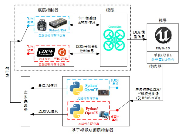
The RflySim platform supports external sensor access, and we divide these sensor data into two categories: one is directly connected to the flight controller's external sensors (magnetic compass, differential GPS, optical flow velocimetry, etc.), and the other is the vision sensor directly connected to the on-board computer (binocal, Lidar, depth camera, etc.) The flight control sensor is directly generated and transmitted to the Pixhawk flight controller through programs such as Simulink, and the vision sensor is generated by the 3D environment engine and transmitted to the on-board computer with the image. RflySim provides the depth camera sensor module SDK for the basic parameters and installation position of the sensor, users can customize the airborne vision module by setting the relevant parameters for the design orientation, focal length, field of view, etc. of the UAV-borne vision sensor. According to the input/output interface protocol of decision-making, the input/output interface of the decision-making system is provided.

In this lecture Core,Function introduction (Intro) file
The address of the introduction document for this lecture is: 🔗[Installation Directory]\RflySimAPIs\8.RflySimVision\Intro.pdf🔗
In this lecture, API files
In this lecture, the address of the development-related API interface platform is:🔗[Installation Directory]\RflySimAPIs\8.RflySimVision\API.pdf🔗
In this lecture, PPT files
The platform address of the PPT document for this lecture is:🔗[Installation Directory]\RflySimAPIs\8.RflySimVision\PPT.pdf🔗
All routine files in this lecture
For all routines in this lecture, please see the Readme documentation, which is located at:🔗[Installation Directory]\RflySimAPIs\8.RflySimVision\Readme.pdf🔗