4.1. Usage of this chapter
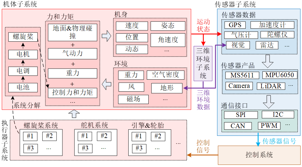
Unmanned vehicle system unified modeling framework divides the whole unmanned vehicle system into two parts: body system and control system. Sensor data and control signals are transmitted between the airframe system and the control system. The airframe system can be subdivided into four subsystems: airframe subsystem, actuator subsystem, three-dimensional environment subsystem and sensor subsystem.
• The airframe subsystem includes internal subsystem modules such as airframe, operating environment, force and moment, which is the overall description of the movement, energy consumption and failure characteristics of the airframe in the environment;
• The actuator subsystem includes the interaction between the vehicle and the external environment. It receives control signals from the control system, and then generates forces and moments to drive the fuselage to move;
• Sensor subsystem is mainly used to describe all electronic hardware models except control software, mainly including sensor data, communication protocol, connection interface and other characteristics;
• The 3D environment subsystem is mainly used to describe the 3D visual environment of unmanned flight (including trees, obstacles, roads, etc.), and is used to provide visual data simulation for the autonomous control system.
In the whole modeling framework, the fuselage system needs to be modeled with high precision and realized in the real-time simulation computer, and finally connected with the software or hardware of the control system to form a software-in-the-loop simulation or hardware-in-the-loop simulation closed loop.

The modeling framework can be rapidly realized in visual modeling and simulation software such as Simulink, after the whole simulation model is built, the simulation software under different real-time simulation computer environments can be generated by using an automatic code generation method, and different types of vehicle models can be rapidly expanded by replacing specific subsystem modules. Shown is an example of a multi-rotor simulation model built in Simulink, which contains basic motion simulation functions and fault injection functions, and can simulate the motion dynamics of various multi-rotors very realistically.
At the same time, RflySim provides Simulink unmanned dynamics modeling template, supports multiple rotor types, facilitates model development and expansion, provides standard input and output interfaces, and can build unmanned models of any configuration in Simulink; Support the automatic code generation of Simulink to be imported into the hardware-in-the-loop simulator in the form of DLL file; The power system component database covers more than 2000 component products on the market, and supports the selection of appropriate motors, propellers and other components from the database to assemble different configurations of multi-rotor (three, four, six, eight rotors) and estimate the performance (hovering time, maximum thrust, etc.) and model parameters (mass, moment of inertia, propeller thrust coefficient, etc.) for multi-rotor dynamic simulation.
In this lecture Core,Function introduction (Intro) file
The address of the introduction document for this lecture is: 🔗[Installation Directory]\RflySimAPIs\4.RflySimModel\Intro.pdf🔗
In this lecture, API files
In this lecture, the address of the development-related API interface platform is:🔗[Installation Directory]\RflySimAPIs\4.RflySimModel\API.pdf🔗
In this lecture, PPT files
The platform address of the PPT document for this lecture is:🔗[Installation Directory]\RflySimAPIs\4.RflySimModel\PPT.pdf🔗
All routine files in this lecture
For all routines in this lecture, please see the Readme documentation, which is located at:🔗[Installation Directory]\RflySimAPIs\4.RflySimModel\Readme.pdf🔗