Other remote control configuration
1. General configuration description
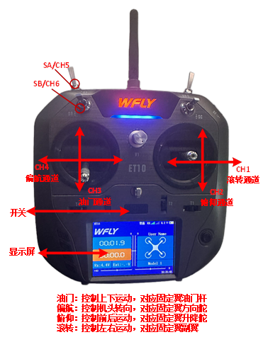
The remote control used in this course is recommended to use the "American hand" control mode, that is, the left rocker corresponds to the throttle and yaw control amount, while the right rocker corresponds to the roll and pitch. The roll, pitch, throttle and yaw in the remote control correspond to the CH1~CH4 channel of the receiver respectively, and the left and right upper side lever corresponds to the CH5/CH6 channel to trigger the flight mode switch.
The throttle rod (CH3 channel) corresponds to the PWM signal fluctuation from 1100 to 1900 from the bottom end and the top end respectively (different channels or different remote controls will be different, so need to be calibrated); Roll (CH1 channel) and yaw (CH4 channel) rockers from leftmost end to rightmost end correspond to PWM signals from 1100 to 1900; The pitch (CH2 channel) rocker corresponds to the PWM signal from 1900 to 1100 from the bottom to the top; The CH5/6 is a three-segment switch, from the top (the gear closest to the user) to the bottom (the gear closest to the user) corresponding to the PWM signal 1100, 1500 and 1900.
2. Configuration and calibration methods are as follows:
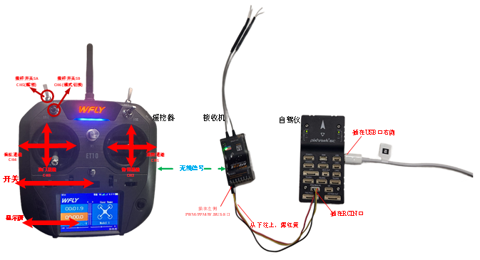
Connect Pixhawk to the receiver correctly, use USB cable to connect Pixhawk to the computer, open the remote control, open the QGroundControl ground station software, click the "Radio" (remote control) TAB as shown in the picture below on the right.
Click the CH1 to CH5 channels (see top right) of the remote control from left to right (or top to bottom), and observe the white dots of each channel in the red box area on the right side of the ground station in the bottom right. If you observe that dots 1, 2, 4, 5, 6 move from left to right (PWM from 1100 to 1900); Dot 3 moves from right to left, indicating that the remote control is set correctly. Otherwise, you need to reconfigure the remote control.
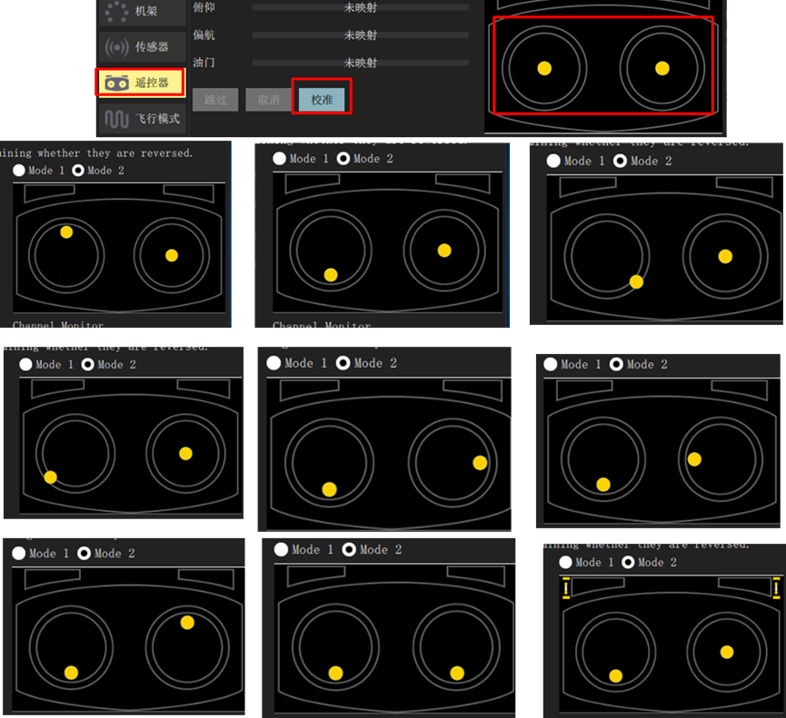
Click the "Calibrate" button on the bottom right and follow the prompts to calibrate the remote control.
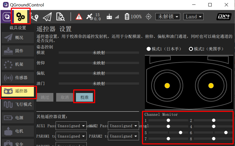
Click the "Calibrate" - "Next" button on the QGC ground station, and then place the rocker in the position shown on the right (according to the real-time prompts on the QGC page) to complete the remote control calibration.
Airplane mode setting
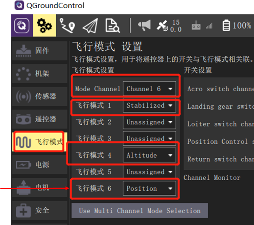
After the above remote control calibration step, click the ground station to enter the "Flight Modes" setting page, and select "Mode Channel" as the Channel 6 channel tested above. Since the CH6 channel is a three-segment switch, the top, middle and lower gears of the switch correspond to the three labels of "Flight Mode 1, 4 and 6" respectively.
The three labels are set to "Stabilized" (self-stabilized mode with only attitude control), "Altitude" (fixed altitude mode with attitude and altitude control), and "Position" (fixed altitude mode with attitude, fixed altitude, and horizontal position control). In the subsequent hardware-in-the-loop simulation, different control effects can be experienced by switching different modes.
